

Surge-arrester protective level alone does not define transformer terminal stress; lead length, grounding conductor inductance and physical separation add voltage during a steep surge. An arrester mounted far from the transformer may therefore protect less effectively than its catalog residual voltage suggests. Insulation coordination should model location, connection length, grounding and incoming line/cable behavior together.
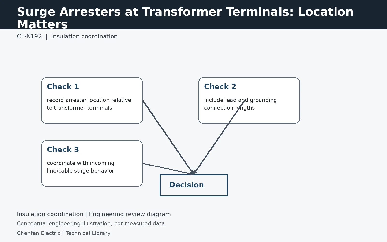
The arrester catalogue value is not the complete terminal voltage
The transformer can experience the arrester's residual voltage plus additional voltage associated with the connecting and grounding paths, with travelling-wave effects where separation is significant. For a simple inductive illustration, V = L di/dt: 1 microhenry with a current change of 5 kA per microsecond gives 5 kV. This does not specify an allowable lead length, but shows why a short-duration steep current can create a meaningful voltage across a seemingly small inductance.
Use the complete surge-current loop
The phase lead, arrester body connection and return to the transformer grounding reference all contribute to the installed arrangement. A nearby arrester with an unnecessarily long or poorly routed earth connection may not perform as assumed in a simplified drawing. The site and transformer suppliers should agree the physical geometry and connection boundary. For cable or GIS interfaces, include reflections and propagation rather than reducing protection to the straight-line distance between two pieces of equipment.
Coordinate protective level with arrester survival
A lower residual voltage is attractive only if the arrester also withstands the maximum continuous operating voltage, temporary overvoltages and required energy or charge duty. Obtain the relevant manufacturer curves and evaluate them against the same system cases used for transformer insulation. The accepted solution should identify arrester type, ratings, location and installation assumptions. Moving the arrester later can invalidate the coordination even when the product itself is unchanged.
Technical reference framework
[1] IEC 60071-1:2019 — Insulation co-ordination, Definitions, principles and rules.
[2] IEC 60071-2:2023 — Insulation co-ordination, Application guidelines.
[3] IEC 60076-3:2013 + AMD1:2018 — Insulation levels, dielectric tests and external clearances.