

After an earthquake, the transformer’s position and support connections need their own inspection record. A dry tank can coexist with displaced supports, cracked grout or concealed anchorage damage. The inspection should identify evidence and unresolved conditions; an absence of visible damage is not a structural clearance to re-energize. [1] [2]
Establish a safe, controlled inspection condition
Use the site’s electrical isolation and access procedures before approaching equipment. Preserve photographs and position measurements before adjustments obscure the event evidence. Coordinate with the responsible equipment and structural teams where damaged connections or unstable parts are suspected.
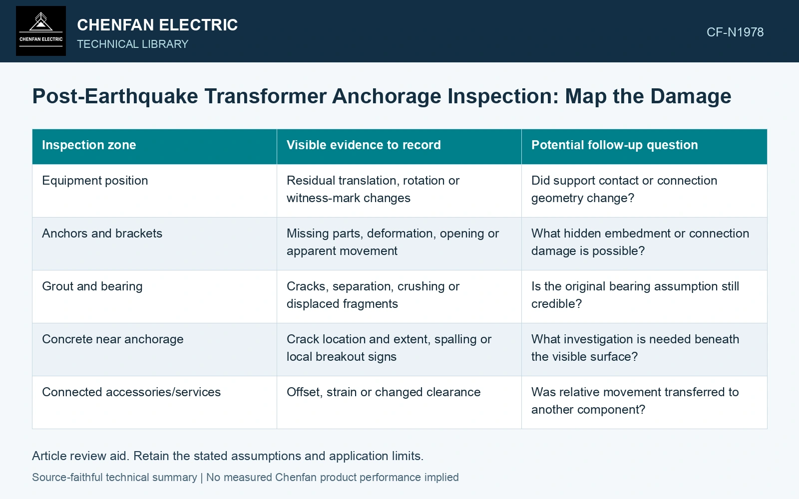
| Inspection zone | Visible evidence to record | Potential follow-up question |
|---|---|---|
| Equipment position | Residual translation, rotation or witness-mark changes | Did support contact or connection geometry change? |
| Anchors and brackets | Missing parts, deformation, opening or apparent movement | What hidden embedment or connection damage is possible? |
| Grout and bearing | Cracks, separation, crushing or displaced fragments | Is the original bearing assumption still credible? |
| Concrete near anchorage | Crack location and extent, spalling or local breakout signs | What investigation is needed beneath the visible surface? |
| Connected accessories/services | Offset, strain or changed clearance | Was relative movement transferred to another component? |
A photograph and a bolt torque are different evidence
Photographs document accessible conditions at a point in time. They cannot establish the integrity of an embedded anchor or concealed bearing surface. Do not convert a visual inspection into a quantified residual capacity without the necessary investigation and assessment.
Do not treat routine re-tightening as proof. Torque depends on friction and connection state, as NASA’s fastener manual explains [3]; turning a damaged fastener can also alter evidence. Preserve the as-found state and use the approved investigation/repair procedure.
Link observations to further investigation
Residual displacement, new cracking, separation, distorted brackets or displaced bearing zones are reasons to refer the affected load path for structural review. The required examination depends on the anchor type, material, access and observed mechanism. No single inspection method can answer every concealed-damage question.
Record uncertainty explicitly when a zone is inaccessible or the original installation dimensions are unavailable. Compare as-found measurements with credible pre-event records, accounting for their accuracy. A difference inferred from an undocumented photograph may be useful for investigation but is weaker than a traceable dimensional baseline.
Assume post-event measurements show base translation 4 mm, anchor permanent elongation 1 mm and an adjacent pipe clearance reduced from 12 mm to 7 mm. The 5 mm clearance loss is not explained by the 4 mm base translation alone; relative accessory, support or pipe motion remains unresolved. Map each measurement to its datum and inspect the full load path before declaring the anchor repair sufficient. Record this as a geometry/damage discrepancy requiring engineering disposition, not as an automatic transformer re-energisation criterion.
Refer each damaged or inaccessible support zone to the examination needed to resolve it, preserving the as-found photographs and measurements. Equipment diagnostics, electrical suitability and structural return-to-service decisions need their own evidence. An exterior leak check cannot settle the anchorage question.
References
- FEMA and Applied Technology Council, FEMA E-74, Reducing the Risks of Nonstructural Earthquake Damage—A Practical Guide, December 2012, section 6.4.7.3, Transformers.
- IEEE, IEEE 693-2018, IEEE Recommended Practice for Seismic Design of Substations.
- R. T. Barrett, Fastener Design Manual, NASA Reference Publication 1228, 1990.