

Collision is governed by the motion between adjacent surfaces. Separate absolute peak displacements do not identify when those surfaces approach each other, and their peak values may occur at different times. The clearance assessment needs a compatible relative-motion definition. [1]
Define the surfaces and the direction that closes the gap
Identify the nearest relevant surfaces, their installed gap and the movements that can reduce it. Translation, rotation and local bending can all matter at an elevated accessory. A displacement recorded at the attachment is not necessarily the displacement at the closest projecting point.
For compatible time histories in one chosen gap-closing direction, relative displacement is urel(t) = uA(t) − uB(t). Define the sign and project the motions onto that direction. Rotating or deforming geometries may require a fuller surface-position evaluation.
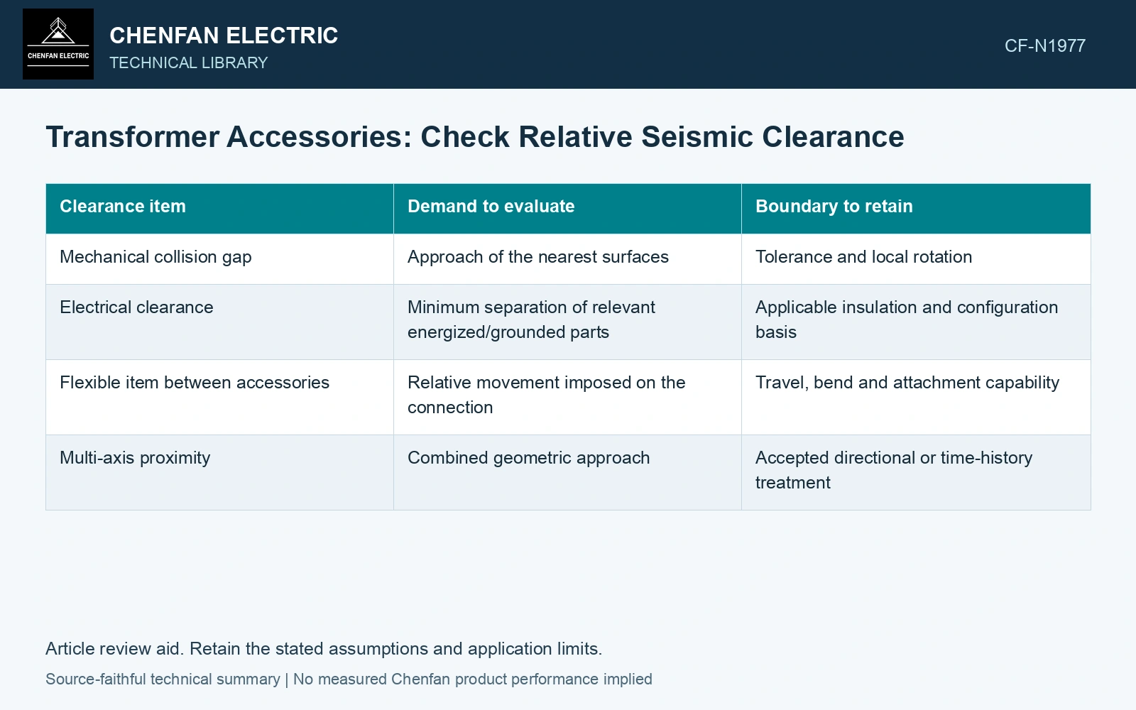
| Clearance item | Demand to evaluate | Boundary to retain |
|---|---|---|
| Mechanical collision gap | Approach of the nearest surfaces | Tolerance and local rotation |
| Electrical clearance | Minimum separation of relevant energized/grounded parts | Applicable insulation and configuration basis |
| Flexible item between accessories | Relative movement imposed on the connection | Travel, bend and attachment capability |
| Multi-axis proximity | Combined geometric approach | Accepted directional or time-history treatment |
Asynchronous motion changes the relative result
Accessory/support phase relationships affect the gap. Independent positive peak magnitudes cannot reconstruct approach. NRC’s modal/spatial-combination guide discusses correlation and multi-support motion [2]; select the project’s compatible time-history or combination treatment, rather than silently mixing maxima.
A sum of absolute displacement bounds can be a deliberately conservative screening approach in some geometries. Label it as a bound and state the directions covered. It is not a reconstructed simultaneous response and may be unsuitable where rotation changes the nearest surfaces.
Keep mechanical and electrical decisions separate
A gap sufficient to prevent impact may still be inadequate for the required electrical separation. Conversely, an electrical clearance assessment does not establish the mechanical capacity of a nearby pipe, brace or conductor. Apply each requirement to the geometry and duty it concerns.
Assume accessory A moves +12 mm and neighbouring structure B moves +8 mm along one common axis at the same instant. Relative displacement is 4 mm, leaving 6 mm from an assumed 10 mm initial clearance. If their relevant phase relationship instead gives +12 mm and −8 mm, relative displacement becomes 20 mm and creates 10 mm interference in the same simplified geometry. Use compatible time histories or a justified combination bound; comparing each absolute maximum with the initial clearance independently can miss the relative-contact case.
The final clearance envelope should include the initial tolerance range, motion representation and minimum predicted separation for each relevant pair. Record any inaccessible or undocumented installed dimension. The result can then identify which pair needs a revised layout, better measurement or more detailed analysis, without relying on unrelated individual displacement limits.
References
- FEMA and Applied Technology Council, FEMA E-74, Reducing the Risks of Nonstructural Earthquake Damage—A Practical Guide, December 2012, section 6.4.7.3, Transformers.
- U.S. Nuclear Regulatory Commission, Regulatory Guide 1.92, Combining Modal Responses and Spatial Components in Seismic Response Analysis, Revision 3, October 2012, sections C.1.1 and C.2.