

An SST link can buffer power only through physically accessible conversion paths [1]. Its permitted voltage/current domain determines useful energy; nominal capacitance is not a long-duration backup claim.
The assessment should begin with the energy state and the imbalance it must absorb or supply. Keep input power, output power and losses on the same boundary.
Define the usable voltage range
For assumed constant linear capacitance, integrate VdQ with Q=CV [2] to get E=½CV² in joules. Between permitted Vhi/Vlo, usable ideal difference is ½C(Vhi²−Vlo²). Take voltage/control limits from the actual design.
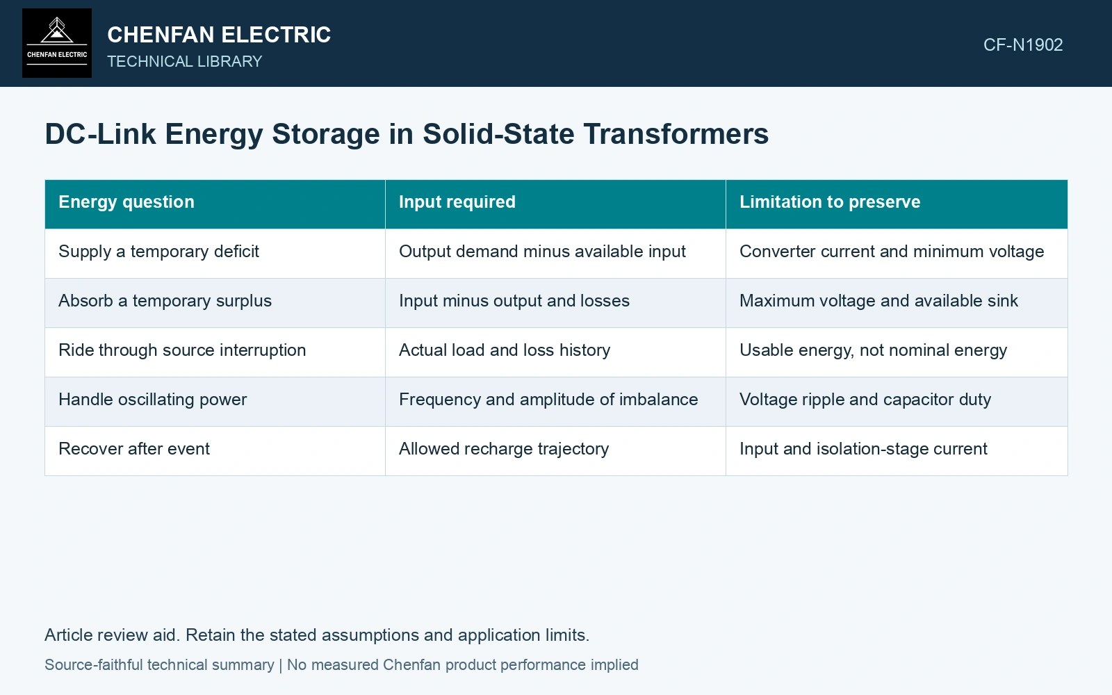
| Energy question | Input required | Limitation to preserve |
|---|---|---|
| Supply a temporary deficit | Output demand minus available input | Converter current and minimum voltage |
| Absorb a temporary surplus | Input minus output and losses | Maximum voltage and available sink |
| Ride through source interruption | Actual load and loss history | Usable energy, not nominal energy |
| Handle oscillating power | Frequency and amplitude of imbalance | Voltage ripple and capacitor duty |
| Recover after event | Allowed recharge trajectory | Input and isolation-stage current |
Put the power balance into the model
At a defined link, dE/dt = Pin − Pout − Ploss. All powers are in watts and time is in seconds. Under an illustrative constant net deficit Pdef, the ideal support interval is ΔE/Pdef. This ignores changed losses and assumes the converter remains within its operating domain throughout.
A small voltage drop can consume a significant control margin even while energy remains. A link may therefore reach a functional or protection boundary before an arithmetic energy budget is exhausted.
Include both ends of the event
Recharging creates another duty. The input stage and isolated stage must support it while serving the continuing load. An energy buffer does not erase that later power requirement. The model should preserve any recharge limit and the initial state of a subsequent event.
The conversion-stage review locates DC links in specific modular paths [1]. Identify which link can actually feed the affected port during the event; an inaccessible energy store cannot be added to that port’s budget.
State the buffer’s job precisely
A useful design statement names the imbalance waveform, starting voltage, permitted range and converter conditions. It can distinguish disturbance buffering from sustained supply and from power-ripple absorption.
Assume 2 mF, initial 800 V and a permitted 700 V floor: usable energy is 150 J versus 640 J initially stored. For an assumed constant net deficit 10 kW, already including conversion losses at this boundary, the ideal interval is 15 ms. Do not add those losses again. Using all 640 J would predict 64 ms, 4.27 times too long. Hold a duty exceeding the usable interval until actual voltage/current limits, loss variation, accessible replenishment and recharge trajectory are resolved.
This avoids two misleading claims: counting all nominal capacitor energy as usable, and interpreting a short supported interval as general backup capability. The energy equation is transparent; its value comes from applying the real voltage and power boundaries rather than leaving them implicit.
References
- D.-M. Predescu and Ș.-G. Roșu, Solid State Transformers: A Review—Part I: Stages of Conversion and Topologies, Technologies 13, 74, 2025. DOI: 10.3390/technologies13020074.
- U.S. Department of Energy, DOE-HDBK-1011/2-92, Electrical Science, Volume 2, 1992.