

A transfer model should be as simple as the decision permits and as detailed as the governing behavior requires. Removing a component is justified only if its omission does not invalidate the quantities used for approval. Minimum therefore refers to evidence coverage, not a fixed number of blocks. [1]
Begin with continuity, reconnection duty, voltage recovery or protection. Liao et al. compare an induction-motor voltage-sag analytical model with PSCAD/EMTDC [2]; that comparison defines a modelling domain, not validation of every site’s rundown and transfer torque.
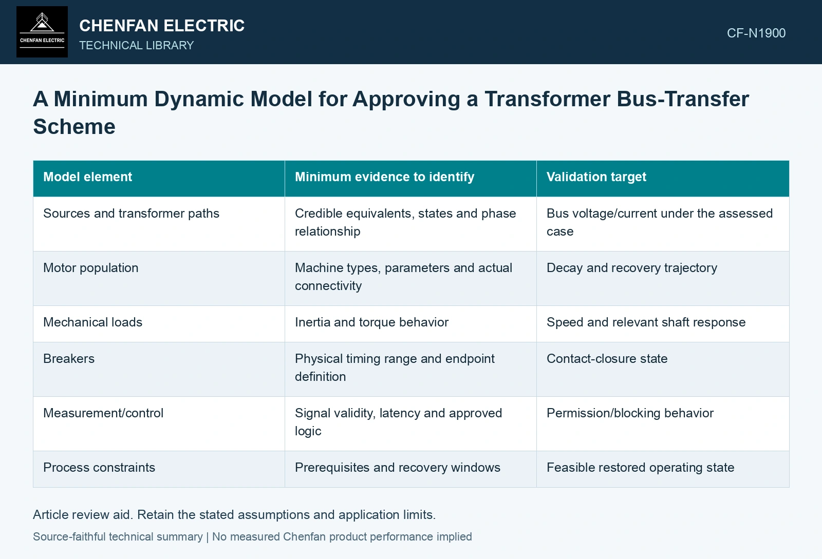
Define the model boundary by consequence
| Model element | Minimum evidence to identify | Validation target |
|---|---|---|
| Sources and transformer paths | Credible equivalents, states and phase relationship | Bus voltage/current under the assessed case |
| Motor population | Machine types, parameters and actual connectivity | Decay and recovery trajectory |
| Mechanical loads | Inertia and torque behavior | Speed and relevant shaft response |
| Breakers | Physical timing range and endpoint definition | Contact-closure state |
| Measurement/control | Signal validity, latency and approved logic | Permission/blocking behavior |
| Process constraints | Prerequisites and recovery windows | Feasible restored operating state |
The table is not a request to derive every model from scratch. It identifies what must remain traceable when a supplier provides an equivalent or a validated component block.
Separate measurements from assumptions
Mark each input as measured, manufacturer supplied, inferred or assumed. Give important assumptions a range and explain which result they influence. A model can produce precise output while relying on uncertain torque, control or breaker data.
Where one equivalent motor represents a group, show the comparison supporting that reduction. Where a source is represented as an ideal voltage, show that its impedance omission does not invalidate voltage recovery or fault behavior.
Validate the quantities that govern approval
Matching a starting-current value does not establish residual-voltage phase evolution. Matching a rundown magnitude does not establish reconnection shaft torque. Select validation targets that correspond to the actual decision, and preserve evidence gaps.
The SEL transfer paper compares its machine model with manufacturer information and replays dynamic signals to transfer logic. Its specific single-motor case illustrates two separate validations: physical model behavior and control response. Neither should silently stand in for the other.
Include credible adverse cases
Review relevant source weakness, load states, delay scatter, protection events and invalid signals. An approved normal case cannot establish behavior in an unmodeled fault or failed control state. Avoid expanding a successful simulation into a complete product or site qualification claim.
Assume signed source-to-residual-bus frequency difference stays +2 Hz and angle is +10° at command. A 50 ms close adds 36°, reaching 46°. With assumed closing-time scatter 40–60 ms, the closure range is 38.8–53.2°. A fictional 50° review cap passes the nominal delay but fails the slow end: hold approval based on the nominal-only replay. Use actual frequency trajectories, breaker scatter and motor/network dynamics; these assumptions are not source transfer thresholds.
The model package should contain the boundary, input provenance, case coverage and validation results with their limits. A reviewer can then see whether an omitted detail matters to the proposed transfer. That is the smallest defensible model: one that retains the physics and events capable of changing the decision, rather than one made small by assuming those events away.
References
- P. Muralimanohar, D. Haas, J. R. McClanahan, R. T. Jagaduri and S. Singletary, Implementation of a Microprocessor-Based Motor Bus Transfer Scheme, IEEE PCIC, 2016, DOI: 10.1109/PCICON.2016.7589248.
- W.-P. Liao, Y. Zhang and R. Zhou, Analytical method to calculate transient responses of induction motor load, IET Generation, Transmission & Distribution, 2020, DOI: 10.1049/iet-gtd.2018.6107.