

An ISOP SST places modules in series at the input and in parallel at the output. The input voltage is distributed among cells, while their outputs share a common bus. These connections create constraints, but they do not automatically establish equal stress or equal power in every cell.
The review needs three quantities for each module: input/link voltage, output current and stored-energy state. A total terminal measurement can conceal an overloaded cell.
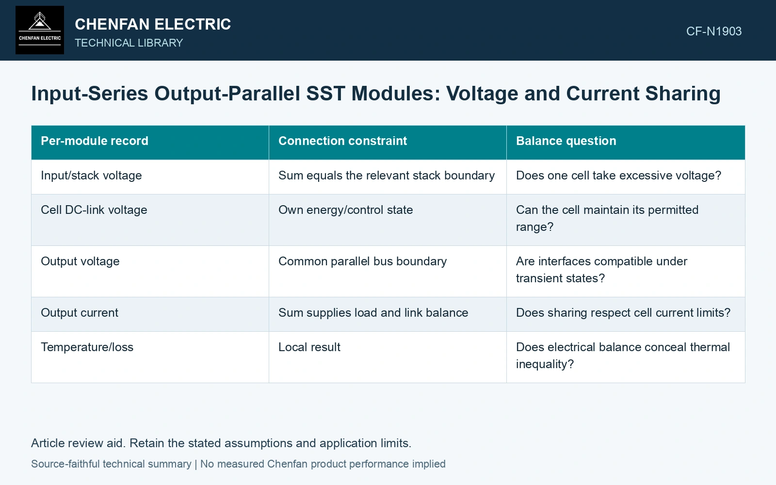
Write the connection constraints first
The series-side cell voltages sum to the applied stack voltage under a consistent instantaneous reference. The parallel outputs share a terminal voltage, while their currents sum to the load current. Equal sharing is a separate behavior to establish.
| Per-module record | Connection constraint | Balance question |
|---|---|---|
| Input/stack voltage | Sum equals the relevant stack boundary | Does one cell take excessive voltage? |
| Cell DC-link voltage | Own energy/control state | Can the cell maintain its permitted range? |
| Output voltage | Common parallel bus boundary | Are interfaces compatible under transient states? |
| Output current | Sum supplies load and link balance | Does sharing respect cell current limits? |
| Temperature/loss | Local result | Does electrical balance conceal thermal inequality? |
The actual AC/DC and isolated stages determine which voltage is being balanced. Do not interchange input waveform voltage and DC-link voltage because both are reported in volts.
Follow each cell’s energy
For cell k, dEk/dt = Pin,k − Pout,k − Ploss,k. Energy Ek is in joules and powers in watts. Unequal losses or power allocation can move link voltages even when the stack terminal looks correct.
The balance mechanism can come from topology, control or both. Preserve the actual input-series voltage constraints and output-parallel current paths when testing module sharing, rather than assuming that a symmetric connection guarantees equal stress during every disturbance. [1][2]
Test unequal cells deliberately
Evaluate credible component tolerances, cooling differences, sensor offsets and load steps. A control that shares current at one operating point may encounter a limit elsewhere. When a cell saturates, the remaining allocation must be assessed rather than extrapolated from the balanced case.
Replacement cells can introduce different loss and control characteristics. Matching nominal port ratings alone does not establish compatibility with the balancing scheme.
Keep global and local acceptance linked
A successful output-voltage test verifies one global result. The qualification record should also preserve each cell’s voltage, current and relevant thermal envelope under the assessed cases.
For a lossless steady DC-DC ISOP screen, assume four cells, input 8 kV and output 400 V/400 A. Total 160 kW requires common series input current 20 A. If one input share is 2.2 kV, it receives 44 kW and can steadily supply 110 A output; the other equal 1.9333 kV shares supply 96.667 A each. A candidate 130/90/90/90 A split at those input voltages therefore cannot remain steady: the first cell demands 52 kW against 44 kW input, an 8 kW local deficit. Reject that as a balanced operating point and resolve link-energy dynamics/control limits. Actual losses and AC modulation require the selected topology’s model.
That record lets a reviewer see whether total power was achieved by an acceptable distribution or by quietly pushing one module beyond its intended state. ISOP is a useful connection architecture. Its capacity claim is strongest when the cell-level balance is demonstrated, not assumed from the series and parallel symbols.
References
- J. E. Huber and J. W. Kolar, Solid-State Transformers: On the Origins and Evolution of Key Concepts, IEEE Industrial Electronics Magazine 10(3), 2016. DOI: 10.1109/MIE.2016.2588878.
- D.-M. Predescu and Ș.-G. Roșu, Solid State Transformers: A Review—Part I: Stages of Conversion and Topologies, Technologies 13, 74, 2025. DOI: 10.3390/technologies13020074.