

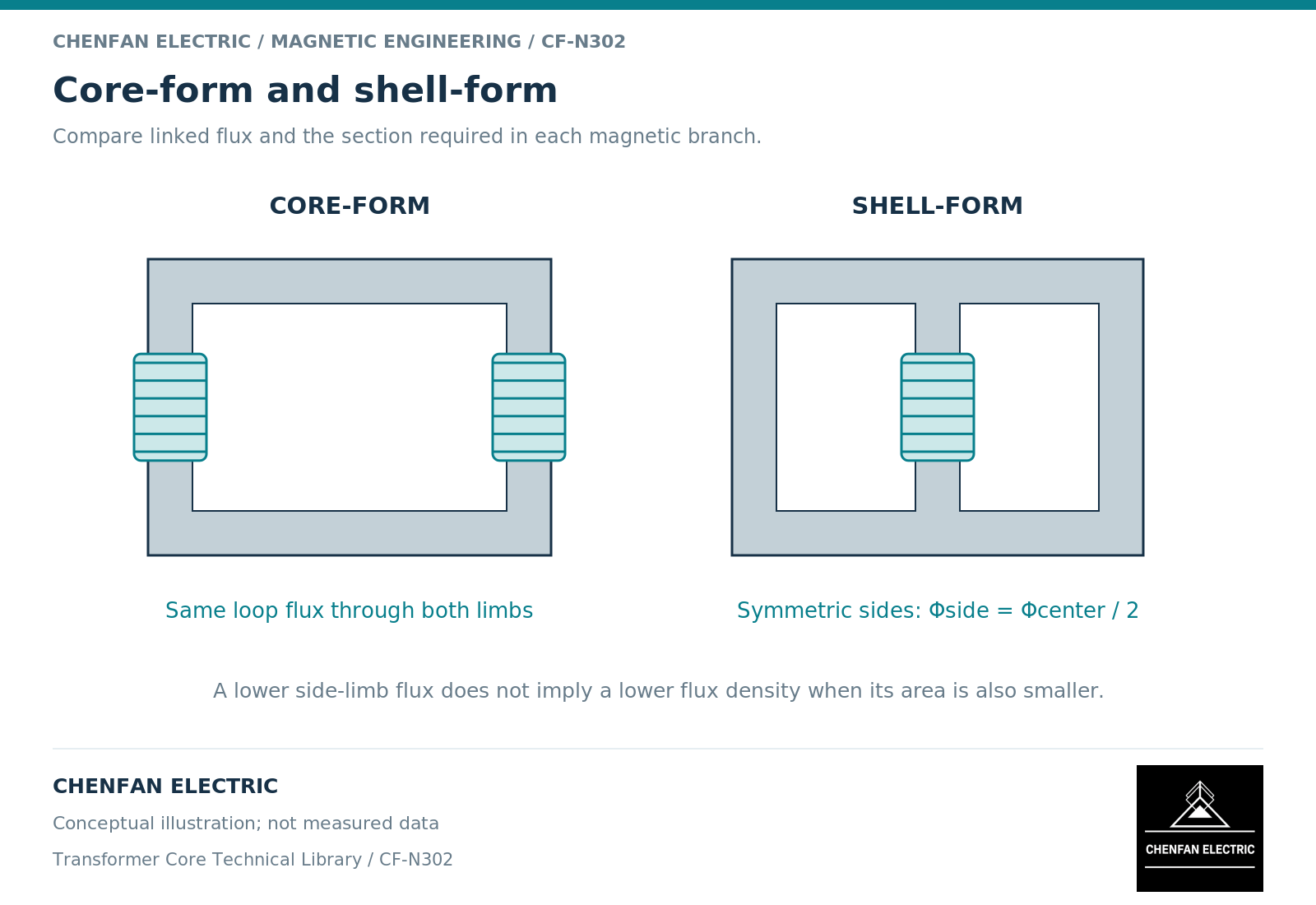
Core-form and shell-form describe how windings and magnetic return paths are arranged, not a universal ranking of transformer quality. In a conventional single-phase core-form arrangement, windings occupy the principal limbs of a closed frame. In a conventional shell-form arrangement, the main winding assembly is associated with a central limb and the flux divides into surrounding return branches. The actual drawing must settle the terminology.
Trace one complete magnetic circuit
Start at a winding and follow the flux through the steel until the path closes. Mark which limbs carry windings, where the return divides and which yoke segments are shared. A shell-form sketch normally shows two return routes around the central wound limb. A core-form sketch normally emphasizes the single frame connecting the wound limbs. Real power-transformer constructions can be more elaborate than either classroom sketch.
The basic relation is magnetic flux continuity. At a branch junction, the algebraic incoming and outgoing fluxes balance. For an ideal symmetric shell arrangement with equal return reluctances, each return branch carries half the central flux. That division is a result of the assumed symmetry, not a rule that every return limb must have exactly half the central area. Nonlinear material properties and unequal branch geometry can change the distribution. [1] [2]
Keep magnetic and electrical comparisons separate
Moving windings changes their physical relationship to the core and to one another. It can affect leakage fields, conductor length, insulation interfaces and the mechanical support arrangement. These consequences must be evaluated using the actual winding layout. The words core-form and shell-form do not specify leakage impedance, impulse distribution, short-circuit strength or temperature rise.
Likewise, magnetic path length alone cannot determine no-load loss. Material condition, flux distribution, joint construction and operating waveform also matter. A topology comparison that changes steel grade, net area and flux density simultaneously cannot attribute its entire loss difference to topology.
A useful comparison therefore has two tracks. The magnetic track evaluates branch flux, excitation and loss. The active-part track evaluates winding arrangement, clearances, cooling and mechanical interfaces. These tracks meet at the released design, but evidence from one does not automatically close the other.
Illustrative branch calculation
Assume a conceptual shell-form circuit has a central peak flux of 0.020 weber and two identical return branches. Flux continuity gives 0.010 weber in each return. If the central net area is 0.0125 square metre, its average peak flux density is 1.60 tesla. A return area of 0.00625 square metre would produce the same average density under the stated equal-sharing assumption.
Now change only one return branch so that the two reluctances are unequal. The equal split can no longer be imposed without checking the magnetic network. In a linear approximation, parallel branches divide flux according to permeance, the reciprocal of reluctance. With saturation, the sharing must be solved at the operating point. The calculation is an illustration of continuity and area, not a production dimension or a measured result.
Build a comparison that a designer can use
Record the following information beside both candidate drawings rather than placing it in unrelated quotation notes.
| Design question | Required comparison basis |
|---|---|
| Where does flux divide? | Named branch paths and the assumed symmetry |
| Which windings share a limb? | Turns, polarity and physical placement |
| What is held constant? | Duty, material basis, waveform and acceptance scope |
| What changes downstream? | Insulation, cooling, supports and assembly access |
For a replacement core, an existing outer envelope is not sufficient proof of compatibility. The winding support surfaces and the magnetic branch definition must also agree with the original equipment manufacturer’s design. A winding that fits mechanically can still have a different leakage-field or cooling environment.
The practical decision is to choose the arrangement that meets the specified electromagnetic and active-part requirements together. A topology label is a useful starting point for that review; it is not evidence of lower loss, lower noise or greater mechanical strength by itself.
References
[1] Lloyd Dixon / Texas Instruments. Magnetics Design 1 – Introduction and Basic Magnetics.
[2] Manitoba Hydro International / PSCAD. The UMEC Approach.