

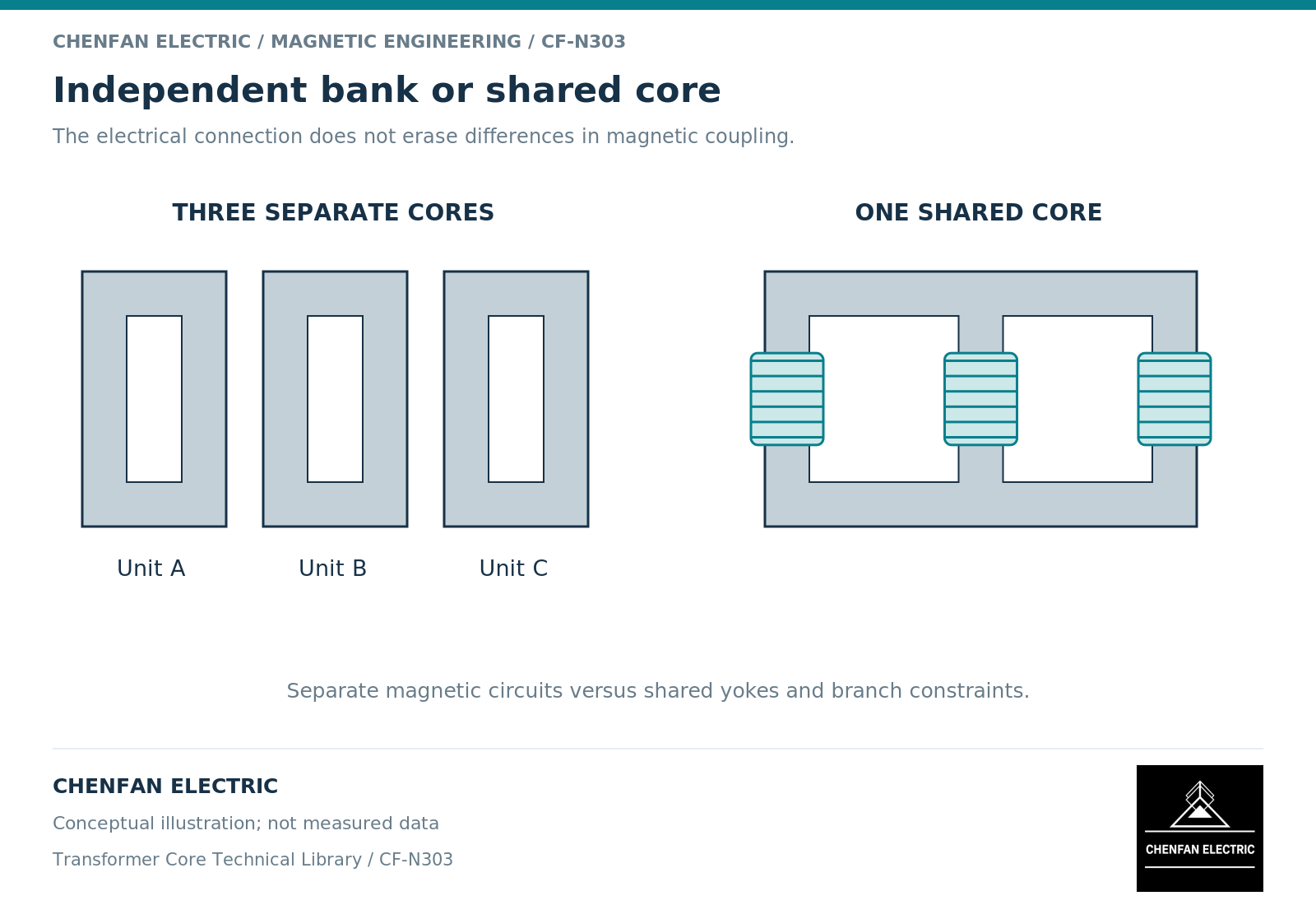
Three separate single-phase transformers and one three-phase transformer can provide the same nominal three-phase voltage ratio while having different magnetic coupling. The separate units have independent core return paths. A shared three-phase core connects phase fluxes through common steel branches. That distinction becomes important when a study moves beyond a balanced steady operating point.
Electrical connection does not define the core network
A three-phase bank is created by connecting the windings of individual single-phase units. Its electrical vector relationship depends on those connections and polarities. Each unit nevertheless retains its own magnetic circuit. In a shared three-phase core, the electrical connections still matter, but the magnetic response of one phase can also involve branches associated with the other phases.
An independent-phase transformer model is therefore not automatically a geometrically faithful representation of a three-limb unit. Geometry-based models account for interphase magnetic coupling as well as coupling between windings on the same phase. The distinction is explicit in the Unified Magnetic Equivalent Circuit approach described by PSCAD. [1]
This does not make independent-phase models useless. They can be appropriate where the study quantity is adequately represented by the chosen equivalent circuit. The important question is whether coupling omitted from the model can change the result being used for a decision.
Choose the comparison case first
For a balanced load-flow calculation, voltage ratio and leakage impedance may dominate the required representation. During unbalanced excitation, the return paths and winding connections become more visible. During energization, initial magnetic states and switching conditions matter. A bank can have separate residual states in its individual cores; a shared core must also satisfy the relationships imposed by its connected magnetic branches.
Replacement planning adds another distinction. Replacing one single-phase unit in a bank requires compatibility of electrical characteristics and the bank arrangement. Replacing the core of a shared three-phase transformer changes a component within one coupled active part. Neither operation can be approved solely from an equal apparent-power rating.
Transport and spare-unit strategy are legitimate commercial considerations, but they should remain separate from the magnetic model. A transport advantage does not establish a zero-sequence characteristic, and a common spare does not prove that an arbitrary unit will share load correctly.
A model-selection example
Consider a conceptual study of energizing one phase while the other phase terminals remain in a specified unenergized state. In a bank, the excited unit’s main flux closes through its own steel circuit. In a three-limb core, flux from the excited limb divides through the connected return network, including other limbs. Their electrical terminations can influence the response.
The illustration does not prescribe an excitation test. It shows why the model boundary must include both the core arrangement and the terminal states. Using three identical isolated inductors for both constructions would erase the difference that the study is intended to investigate. Saturation treatment and leakage representation must then be checked separately. [1] [2]
Handover the distinction explicitly
A comparison record should identify the physical construction before listing equivalent-circuit parameters. Include the number of independent cores, the number of wound limbs per core, the connection of every winding and the interpretation of each supplied impedance. State whether a value describes one phase unit, a three-phase terminal test or a fitted branch in a simulation.
| Study purpose | Bank information | Shared-core information |
|---|---|---|
| Balanced operation | Per-unit ratings and bank connection | Three-phase ratings and connection |
| Unbalanced excitation | Individual return circuits and terminal states | Interphase branches and external return treatment |
| Switching | State and switching history of each unit | Compatible limb states and coupled nonlinear model |
| Replacement | Matching basis for the replacement unit | Active-part and core-interface compatibility |
Keep measured parameters separate from assumed ones. A model can reproduce one terminal test without uniquely identifying its internal magnetic network. Where the intended duty lies outside the evidence, expose that gap rather than assigning the same default parameters to both constructions.
The useful conclusion is a construction-specific model and replacement basis. The choice between a bank and a shared core is not settled by calling one arrangement more modular or more compact; those benefits must be evaluated alongside the magnetic behavior relevant to the project.
References
[1] Manitoba Hydro International / PSCAD. The UMEC Approach.
[2] Manitoba Hydro International / PSCAD. The Classical Approach.