

A missing connection drawing can tempt an engineer to infer the internal pancake arrangement from terminal tests. Ratio, resistance and phase data can exclude many possibilities. They may still leave several electrically equivalent internal designs.
Start with a list of candidate topologies supported by known construction and terminal information. Record each assumption explicitly. Do not draw one attractive diagram and search only for measurements that confirm it.
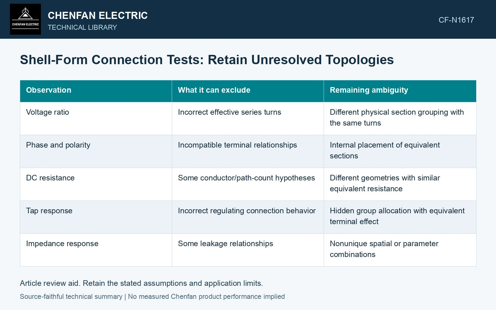
Compare each hypothesis with independent observations
| Observation | What it can exclude | Remaining ambiguity |
|---|---|---|
| Voltage ratio | Incorrect effective series turns | Different physical section grouping with the same turns |
| Phase and polarity | Incompatible terminal relationships | Internal placement of equivalent sections |
| DC resistance | Some conductor/path-count hypotheses | Different geometries with similar equivalent resistance |
| Tap response | Incorrect regulating connection behavior | Hidden group allocation with equivalent terminal effect |
| Impedance response | Some leakage relationships | Nonunique spatial or parameter combinations |
Use qualified test procedures and correct reference conditions. Resistance comparisons require the relevant temperature treatment and conductor information. A ratio result without polarity does not fully describe a connection relationship.
Keep equivalent candidates visible
Two series groups can sometimes be rearranged physically without changing effective terminal turns. Parallel paths with different internal distributions can also yield similar equivalent resistance. Terminal measurements see the network’s accessible behavior, not every internal node.
Classify candidates as incompatible, compatible within measurement capability, or unresolved because a needed observation is unavailable. A small residual difference is not meaningful if it lies below the test’s uncertainty or depends on unverified material assumptions.
Avoid using a highly adjustable parameter model to identify topology. If each candidate can choose arbitrary resistances and inductances, all may fit the same data. Constrain parameters with independently justified geometry or material evidence where available.
Select the next observation for discrimination
Ask which approved additional test or record would separate the remaining candidates. A nameplate, tap schedule, lead identification record or accessible connection photograph may be more informative than repeating the same ratio test with greater numerical precision.
Internal inspection should follow the equipment’s authorized procedures. Do not energize unusual connections simply to make a hypothesis distinguishable. The test plan must remain within safe and approved boundaries.
If ambiguity remains, label the output as a candidate connection model. State which terminal behaviors it reproduces and which internal details are unknown. Use it only for tasks insensitive to those differences, or obtain verified design information for the decision.
A reconstructed diagram is valuable when it narrows a real question honestly. Presenting it as the original manufacturer structure converts an inference into an unsupported fact and can misdirect later fault, thermal or insulation analysis. Keep connection, tapping and network assumptions explicit in the application assessment [1].
Retain two topologies that terminal data cannot separate
Assume a 50 Hz ratio test identifies 80 effective turns and a same-temperature DC test gives 0.20 Ω. Candidate A has four 20-turn, 0.05 Ω pancakes in series: 80 turns and 0.20 Ω. Candidate B has two parallel paths, each with four series 20-turn, 0.10 Ω pancakes: each path has 80 turns and 0.40 Ω, so the parallel equivalent is again 0.20 Ω. Both reproduce those terminal observations despite different physical counts and branch currents. Keep both candidates unless polarity, leakage or construction evidence separates them; repeating the same measurements cannot make the topology unique [2]. Record rated quantities and test conditions on the general power-transformer basis of IEC 60076-1 [3]. Assess the relevant measured quantities with a defined measurement model and propagated uncertainty [2].
References
- IEC, IEC 60076-8:1997, Power transformers – Part 8: Application guide, 1997, official public scope.
- JCGM, JCGM 100:2008, Evaluation of measurement data — Guide to the expression of uncertainty in measurement, 2008.
- IEC, IEC 60076-1:2011, Power transformers – Part 1: General.