

Shell-form pancakes can move normal to their broad faces, within those faces, or rotate as groups. A restraint effective in one direction may offer little resistance in another. The transport review should therefore begin with permitted and restricted motions, not with a total brace count.
Define the shipment orientation and approved load cases. Compare the transport state with the operating assembly: temporary components, liquid condition and installed supports can differ. Do not assume that every operating reaction path remains active during shipment.
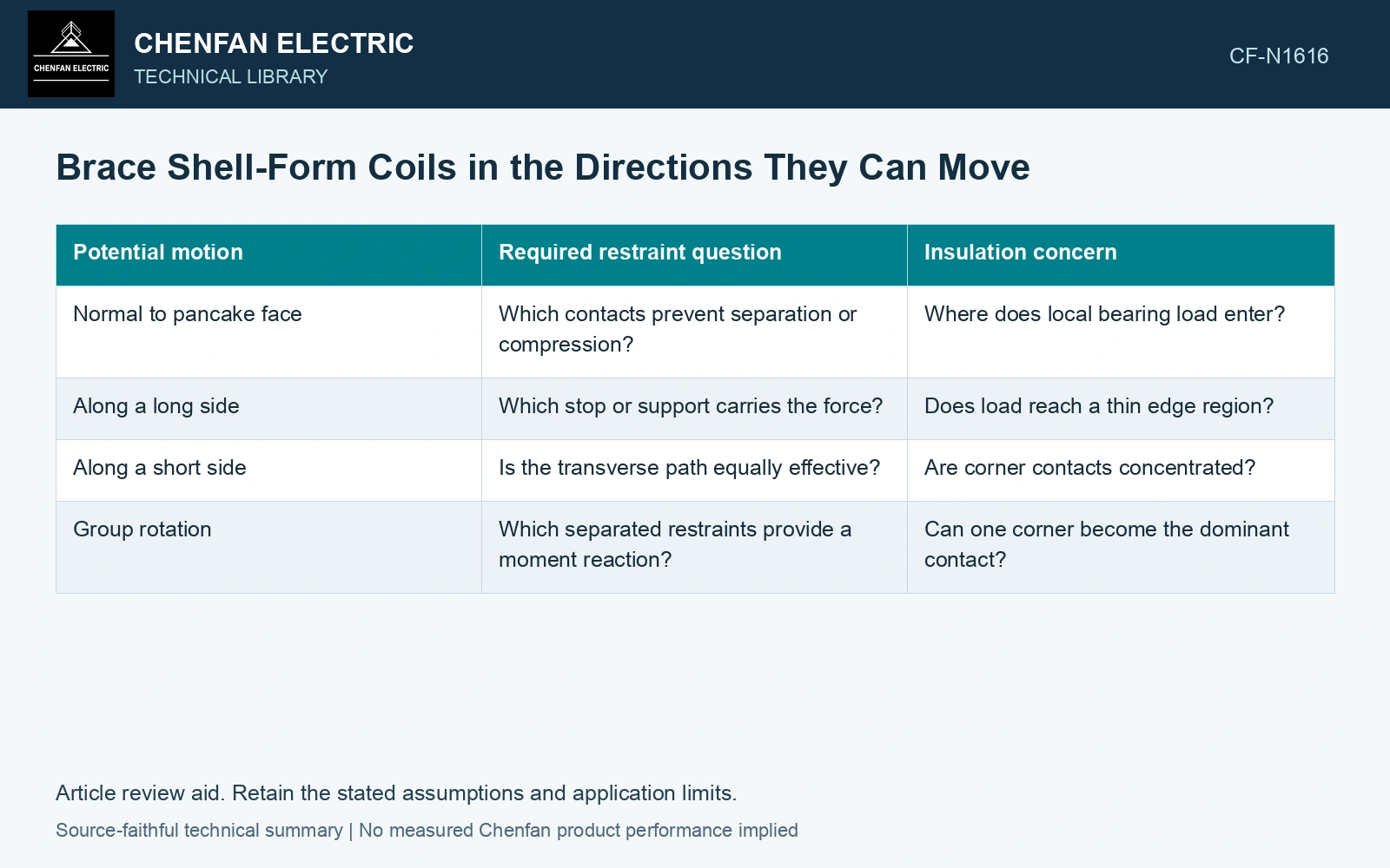
Follow each load direction
For an ideal rigid group of mass m under an acceleration vector a, the inertial force is −ma in the accelerating frame. This defines a load direction, not a complete dynamic shipment model. Rotational motion and structural flexibility may require additional treatment.
| Potential motion | Required restraint question | Insulation concern |
|---|---|---|
| Normal to pancake face | Which contacts prevent separation or compression? | Where does local bearing load enter? |
| Along a long side | Which stop or support carries the force? | Does load reach a thin edge region? |
| Along a short side | Is the transverse path equally effective? | Are corner contacts concentrated? |
| Group rotation | Which separated restraints provide a moment reaction? | Can one corner become the dominant contact? |
Contact can carry compression without carrying tension. A brace that disengages under one load direction should not be represented as a bilateral spring unless the physical fastening provides that function.
Avoid an unintended load shortcut
Trace the force from the coil group through the brace to the structural reaction. If the route passes through an insulation region not qualified for that loading, the brace may protect gross motion while introducing local damage risk.
Include initial gaps and assembly variation. A close brace may engage before another and take most of the load. A brace that appears present on a drawing can be ineffective if its actual contact gap is too large for the permitted movement.
Temporary restraints need an explicit installation and removal state. If a brace must be removed before operation, identify how its removal is verified and whether the coil’s final locating state changes. Do not rely on an undocumented temporary contact to complete the operating support model. Record rated quantities and test conditions on the general power-transformer basis of IEC 60076-1 [1].
Verify the restrained state
Use approved inspection or qualification methods to check contact, fastening and group position. Record the baseline geometry so that a later displacement can be distinguished from an earlier assembly offset.
If shipment observations suggest movement, compare the affected direction with the actual reaction path. Adding a brace elsewhere may increase apparent restraint without addressing the missing direction.
The defensible design explains how each relevant translation and rotation reaches a qualified structural reaction. That direction-specific account is more useful than assuming that a heavily clamped assembly is equally secure against every transport motion.
Turn one shipment load into a directional restraint check
Assume a rigid 2,000 kg coil group under a specified transverse shipment acceleration of 2g, with g taken as 9.81 m/s². The inertial load is 39.24 kN. Four engaged supports with equal load sharing would carry 9.81 kN each; if gaps leave only two engaged, each carries 19.62 kN. For an assumed 1,000 mm² bearing area per support, average pressure doubles from 9.81 to 19.62 MPa. Compare those directional loads with qualified support data and contact engagement. The assumed acceleration is a study input, not an IEC transport requirement [1]. Assess the relevant measured quantities with a defined measurement model and propagated uncertainty [2].
References
- IEC, IEC 60076-1:2011, Power transformers – Part 1: General.
- JCGM, JCGM 100:2008, Evaluation of measurement data — Guide to the expression of uncertainty in measurement, 2008.