

A bank of single-phase units provides a physical substitution opportunity, but capacity alone does not define interchangeability. The spare must work electrically with the remaining units and physically with the installed interfaces.
Start from the bank’s actual connection, tap arrangement and operating requirements. Identify the specific position the spare may occupy. Similar terminal labels can conceal different polarity or grounding relationships.
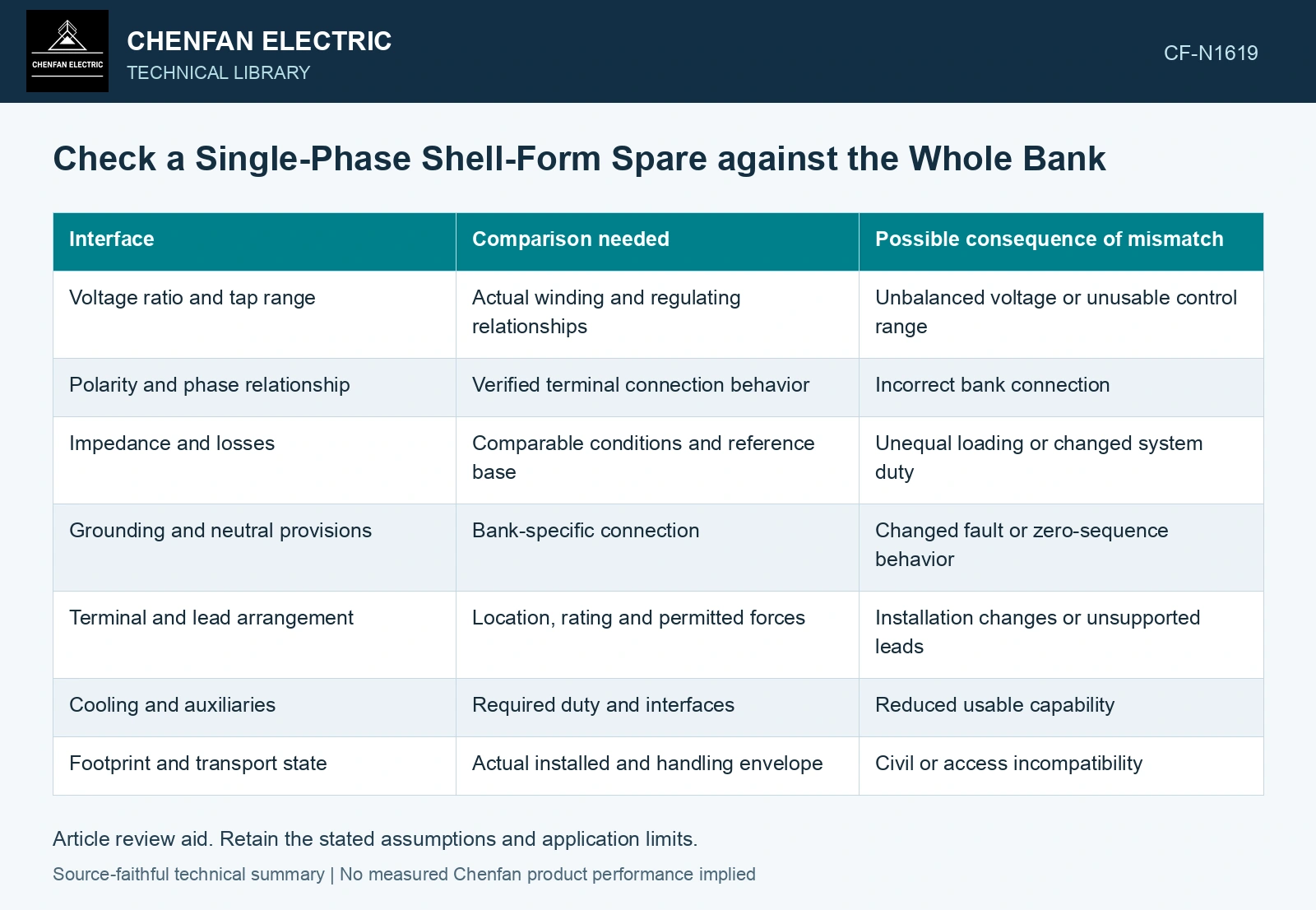
Build an interface comparison
| Interface | Comparison needed | Possible consequence of mismatch |
|---|---|---|
| Voltage ratio and tap range | Actual winding and regulating relationships | Unbalanced voltage or unusable control range |
| Polarity and phase relationship | Verified terminal connection behavior | Incorrect bank connection |
| Impedance and losses | Comparable conditions and reference base | Unequal loading or changed system duty |
| Grounding and neutral provisions | Bank-specific connection | Changed fault or zero-sequence behavior |
| Terminal and lead arrangement | Location, rating and permitted forces | Installation changes or unsupported leads |
| Cooling and auxiliaries | Required duty and interfaces | Reduced usable capability |
| Footprint and transport state | Actual installed and handling envelope | Civil or access incompatibility |
Electrical comparison should use consistent rating bases and temperatures. Percent impedance values on different bases cannot be compared directly without conversion. Include tolerance and the behavior across relevant taps rather than selecting one favorable nameplate value.
Distinguish magnetic independence from system independence
Separate single-phase units have separate cores. That does not make each phase’s system behavior independent. Their electrical connection, grounding and external network couple the bank’s response, particularly under unbalanced or fault conditions.
Use the actual bank model to assess a proposed impedance or regulating difference. Do not borrow a three-phase shared-core assumption or a generic zero-sequence path without checking the arrangement.
Mechanical and auxiliary interfaces deserve equal attention. A terminal route that can be adapted may still require an approved insulation and support redesign. A cooling interface that connects physically may not deliver the required operation.
Classify the differences
Identify direct matches, acceptable differences supported by engineering, and differences requiring modification or further evidence. Keep an unresolved field unresolved rather than accepting a sales description as a verified interface.
Use manufacturer records and qualified tests to confirm critical electrical relationships. A candidate unit’s external appearance cannot establish its internal connection or regulating duty. Keep connection, tapping and network assumptions explicit in the application assessment [1].
The spare decision becomes actionable when the matrix names the limiting interface and the work needed for substitution. A matching capacity is the entry point to that review, not its conclusion. This approach avoids discovering a polarity, tap or terminal constraint only after the original unit has been removed.
Put the candidate spare on the same impedance base
Assume a 50 Hz, 100 kV terminal reference. The installed single-phase unit has 10% impedance on 100 MVA, giving Z = 0.10×(100 kV)²/100 MVA = 10 Ω. A candidate has 12% on 80 MVA, giving 15 Ω on the same terminal reference. On 100 MVA its value is 15%, not 12%, and the ohmic difference is 50%. Under the simplified equal-voltage, leakage-dominated comparison, inverse-impedance currents would be in a 1.5:1 ratio. Flag this as an electrical mismatch for the actual bank study; matching terminal voltage and physical footprint cannot close that review [2]. Record rated quantities and test conditions on the general power-transformer basis of IEC 60076-1 [2]. Assess the relevant measured quantities with a defined measurement model and propagated uncertainty [3].
References
- IEC, IEC 60076-8:1997, Power transformers – Part 8: Application guide, 1997, official public scope.
- IEC, IEC 60076-1:2011, Power transformers – Part 1: General.
- JCGM, JCGM 100:2008, Evaluation of measurement data — Guide to the expression of uncertainty in measurement, 2008.