

A saturable reactor uses magnetic nonlinearity intentionally. Its useful behavior may be a controlled change in inductance or in the portion of a waveform that it supports before entering saturation. Evaluating it with the sole objective of “never saturating” would miss the function it was designed to perform.
Define the controlled characteristic
In an ordinary energy-storage reactor, the design may seek a relatively predictable inductance over a specified current range. In a saturable device, the desired transfer characteristic deliberately uses a change in magnetic state.
Magnetic-amplifier guidance describes an application in which an inductive element supports voltage while unsaturated and becomes much less inductive after saturation, with reset controlling the subsequent behavior. [1] That is one implementation, not a universal circuit for every saturable reactor.
The specification should state the power-circuit waveform, the control or reset arrangement, and the required relationship between control input and power-circuit response. “Saturable core” alone does not define any of these.
Keep the state history in the model
A normal B–H curve does not fully describe a history-dependent switching or control cycle. Remanence, reset, hysteresis and the direction of traversal may affect when the device reaches the intended state. Ferromagnetic modeling guidance distinguishes memoryless constitutive curves from hysteresis models. [2]
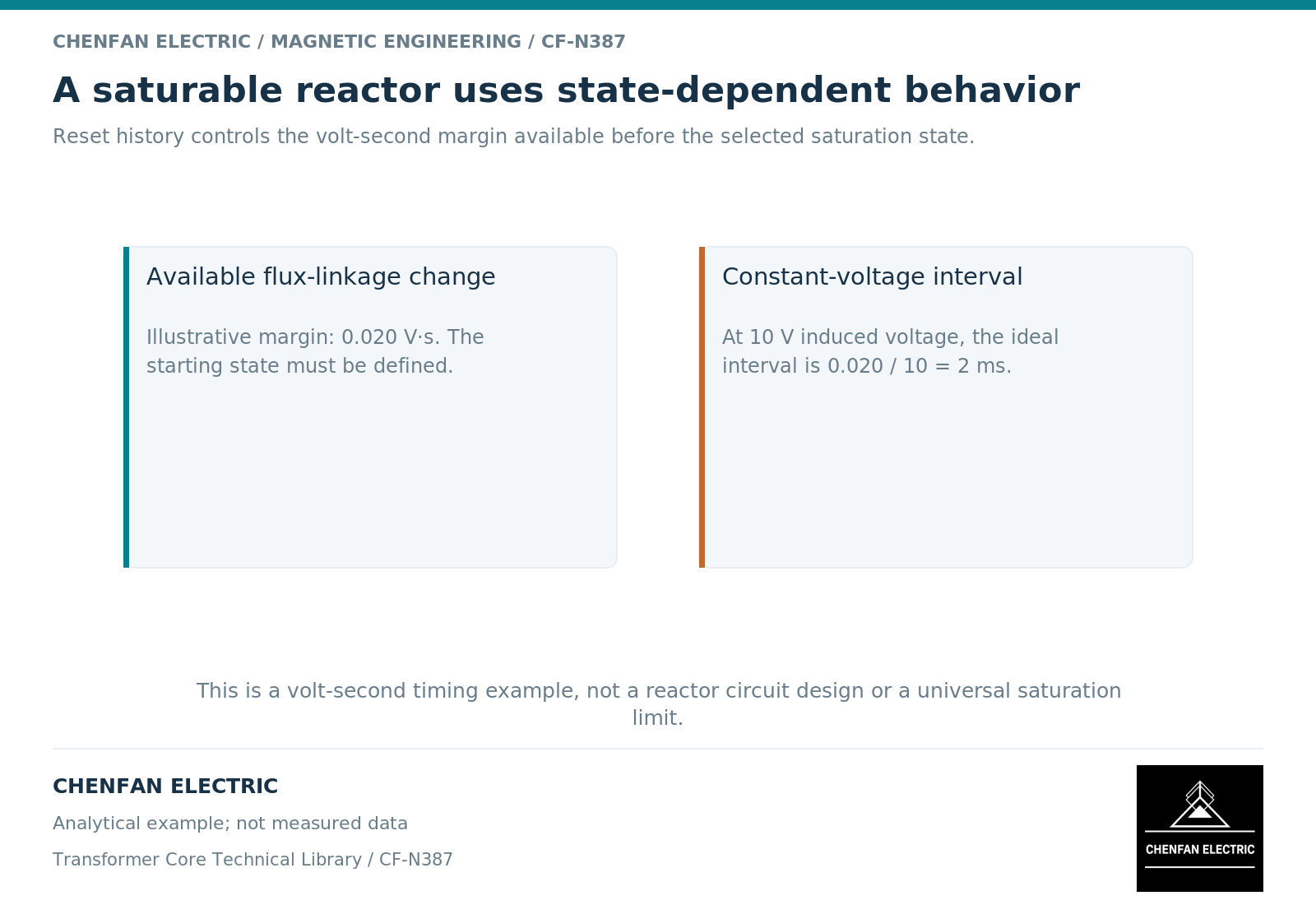
An illustrative ideal flux-linkage interval of 0.020 V·s traversed under a constant induced voltage of 10 V takes 2 ms. The arithmetic follows from the voltage integral. It is not a measured switching delay and excludes winding drops, nonlinear dynamics and the control circuit.
If the initial state changes, the available flux-linkage interval changes. That is why a specified control current without its history or reset condition may be insufficient to reproduce the behavior.
Separate intentional saturation from uncontrolled stress
| Feature | Intentional design requirement |
|---|---|
| Saturation transition | Defined location within the operating cycle |
| Control or reset input | Stated waveform and range |
| Unsaturated response | Required voltage-support or inductive behavior |
| Saturated response | Actual residual impedance and current duty |
| Repetition and temperature | Loss and thermal capability over the cycle |
| Abnormal condition | Equipment-specific protection and recovery requirements |
Saturation does not imply zero impedance or zero loss in the real device. Winding resistance, leakage, material loss and circuit limitations remain. An idealized switch analogy should not be converted into an unlimited-current claim.
The power and control windings, where separate windings are used, must also be assessed for insulation, coupling and thermal duty. A core material choice cannot establish those assembly properties by itself.
Specify evidence against the intended curve
Acceptance should compare the relevant transfer characteristic, timing or impedance behavior under identified operating conditions. A conventional no-load transformer excitation test may provide useful material information but does not by itself verify the controlled function.
A substitute material should be reviewed for loop shape, usable excursion, losses, temperature dependence and manufacturing state, not only nominal permeability. Two cores with similar dimensions and one matching data point can have different cycle behavior.
This is an educational distinction between intentional and unintended nonlinearity. It neither declares a particular saturable-reactor product capability nor supplies a construction circuit. The practical result is a specification centered on the required magnetic cycle rather than on a generic prohibition against saturation.
References
[1] Texas Instruments / Unitrode. Magnetic Amplifier Control.
[2] Cesare Tozzo / COMSOL. Modeling Ferromagnetic Materials in COMSOL Multiphysics.