

A filter reactor specification should begin with the frequency spectrum and circuit function, not a single inductance value or a familiar core grade. The reactor’s impedance, losses and magnetic operating range must remain suitable under the fundamental, relevant harmonics and any transient or bias conditions. A line-frequency material rating cannot answer all those questions.
State what the reactor does in the filter
A reactor may form part of a tuned branch, a detuned capacitor arrangement, a line filter or another network. Manufacturer application lists distinguish alternating-current and direct-current filtering, harmonic filtering and capacitor protection rather than treating all inductors as one duty. [1]
For an ideal linear series inductor-capacitor branch, resonance occurs at f0 = 1/(2π√LC). This is a circuit relationship, not a complete filter-design method. Resistance, source impedance, component tolerances and the connected system affect the actual response.
A change in inductance therefore changes more than the component’s nameplate value. It can move the circuit’s frequency response and alter current duty elsewhere.
Preserve harmonic amplitudes and phase information
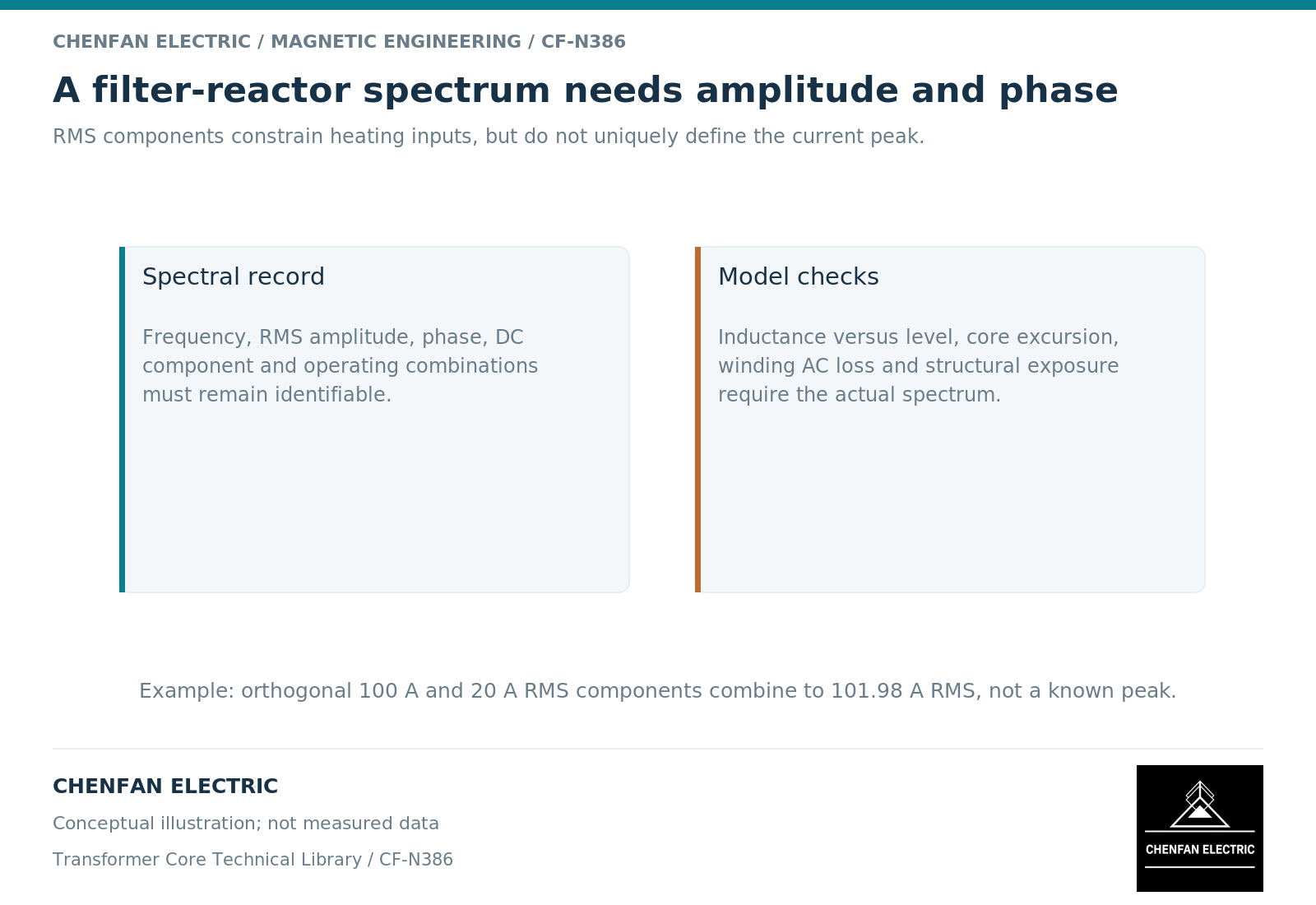
Specify the current spectrum and the voltage waveform relevant to the reactor. Orthogonal harmonic root-mean-square currents can be combined for total root-mean-square magnitude, but that does not reconstruct the peak current or time-domain waveform without phase information.
For an illustrative current containing 100 A fundamental and 20 A third-harmonic root-mean-square components, with no other components, total root-mean-square current is about 101.98 A. The peak is not necessarily √2 times that total; it depends on the harmonic phase relationship.
The magnetic excursion follows the actual circuit and constitutive response. Inductor design guidance separates current, flux swing and loss mechanisms, reinforcing the need for waveform-based inputs. [2]
Specify inductance over the required operating range
| Specification element | Reason |
|---|---|
| Inductance definition and frequency | Avoids comparing unlike measurements |
| Current amplitude and bias | Establishes nonlinear operating range |
| Harmonic spectrum | Defines frequency-dependent magnetic and winding loss |
| Allowed tolerance | Affects filter tuning and system response |
| Thermal duty | Includes continuous and exceptional conditions |
| Insulation and mechanical interfaces | Preserves complete assembly suitability |
A small-signal inductance at one frequency may differ from the effective behavior under large distorted current. The required tolerance should therefore identify the test condition and the operating behavior it supports.
For core materials, use data that cover the relevant excitation trajectory and temperature. Extrapolating a cold-rolled grain-oriented electrical-steel loss value at line frequency to an unrelated high-frequency waveform is not a verified comparison.
Evaluate the reactor with the surrounding network
A proposed core or gap change should be checked for its effect on inductance, loss, saturation behavior and local fringing fields. The system designer should then assess how those changes affect the filter branch and its interaction with the supply.
A lower standalone core-loss estimate is not automatically a better filter if the inductance characteristic moves outside the required range. Similarly, an acceptable thermal result at the fundamental does not establish harmonic-duty performance.
The useful procurement output is a spectrum-based duty envelope with an explicit inductance definition and verification basis. It supports meaningful core selection without suggesting that every transformer-core supplier is qualified to manufacture the complete filter reactor or approve the power-system design.
References
[1] Hitachi Energy. Dry-type inductors and chokes.
[2] Lloyd Dixon / Texas Instruments. Magnetics Design 5 – Inductor and Flyback Transformer Design.