

A winding fault does not automatically condemn the core. It also does not make the core reusable merely because the steel remains in one piece. The repair decision depends on where fault energy went, what was moved during dismantling, and which parts of the original magnetic assembly can still be verified. [1]
Begin by defining the object being retained. Reusing an assembled core, restacking selected laminations and rebuilding with salvaged steel are different projects. Their evidence requirements differ because the first preserves joint history while the others introduce new sorting, handling and assembly variables.
Build a fault-to-core map
Locate the failed winding section relative to the core limb, yoke, window and clamps. Look for credible paths for molten metal, arc products, heat and mechanical force. A winding-to-core arc justifies a different investigation from a turn fault contained inside the coil. Record inaccessible areas rather than treating the visible surface as representative of them.
The map should continue through dismantling. A clamp released for winding removal may permit a joint to open. A lifting operation may disturb an otherwise undamaged packet. These changes belong in the core assessment even if they occurred after the electrical fault.
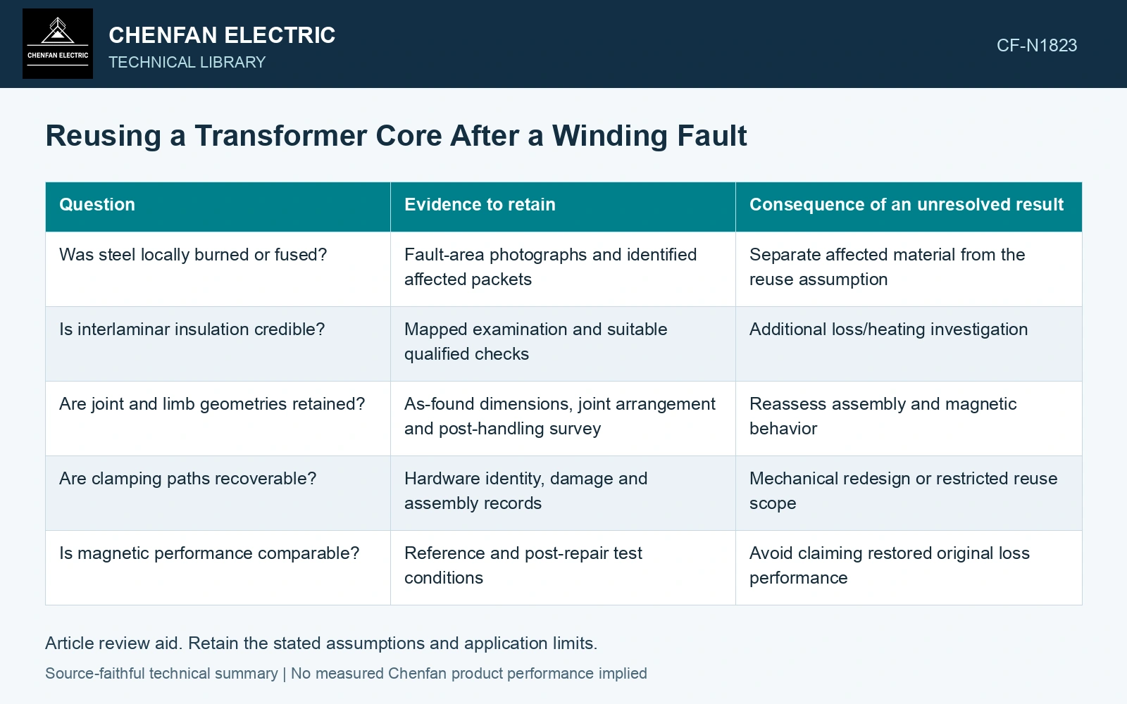
| Question | Evidence to retain | Consequence of an unresolved result |
|---|---|---|
| Was steel locally burned or fused? | Fault-area photographs and identified affected packets | Separate affected material from the reuse assumption |
| Is interlaminar insulation credible? | Mapped examination and suitable qualified checks | Additional loss/heating investigation |
| Are joint and limb geometries retained? | As-found dimensions, joint arrangement and post-handling survey | Reassess assembly and magnetic behavior |
| Are clamping paths recoverable? | Hardware identity, damage and assembly records | Mechanical redesign or restricted reuse scope |
| Is magnetic performance comparable? | Reference and post-repair test conditions | Avoid claiming restored original loss performance |
Do not let one favorable test dominate
A terminal ratio test checks winding relationships; it says little about local core damage. An insulation measurement on an accessible boundary does not establish every lamination interface. Equally, an elevated no-load loss does not by itself identify the damaged packet, because excitation conditions, joint geometry and assembly stress also influence the result.
Use tests to answer defined questions. For example, if the concern is a disturbed step-lap joint, the inspection should preserve the joint layout and assembly condition, and the magnetic comparison should control voltage, frequency and waveform. If molten metal reached the window, the assessment should identify possible bridging and contamination paths. A generic pass/fail sheet misses those distinctions.
Compare post-fault loss on a declared steel basis
Nippon Steel lists 23ZH85 maximum new-strip loss of 0.85 W/kg at 1.7 T, 50 Hz. [2] Assumptions: the identified steel mass is 2,000 kg and the matched assembled-core reuse test gives 2.04 kW. The strip-catalogue basis is 1.70 kW. An assumed project assembly-loss budget of 1.25 times that basis is 2.125 kW, so the total result passes that budget by 85 W. However, an assumed matched pre-fault assembled result of 1.98 kW makes the rise 60 W, or 3.03%. Against a separate assumed ≤2% change gate, the allowable result is 2.0196 kW and the reuse test fails by 20.4 W. Hold unconditional reuse and investigate the mapped disturbed regions. Passing a total-loss budget does not clear a significant baseline shift; neither test uniquely locates damaged steel. Catalogue limits concern new strip, not retained material or a transformer guarantee. [1][2]
Packet displacement, burr bridges, joint overlap, rolling direction and clamp pressure control the rebuilt magnetic path. Map disturbed locations before reassembly so a later loss change can be related to physical construction rather than visual appearance.
References
- U.S. Bureau of Reclamation, FIST Volume 3-31, Transformer Diagnostics, June 2003.
- Nippon Steel Corporation, Grain-Oriented Electrical Steel Sheets, catalogue D004je, April 2020, specification and typical-property tables.