

A pulsing ground-fault locator changes a current component so that a faulted path can be distinguished from background. That change occurs within an existing grounding circuit. Its meaning depends on where the base current and added modulation flow, and on what the detector actually measures. [1]
The circuit review should start with the manufacturer’s verified scheme. Pulsing systems can use different arrangements; a generic sketch cannot establish a particular unit’s current magnitude or switching duty.
Separate the base and changing components
Identify the fault current before modulation, the added or altered component during each pulse and the return path. Keep the resistor and switching-device boundaries distinct. A device can carry a different current waveform from the NGR element bank.
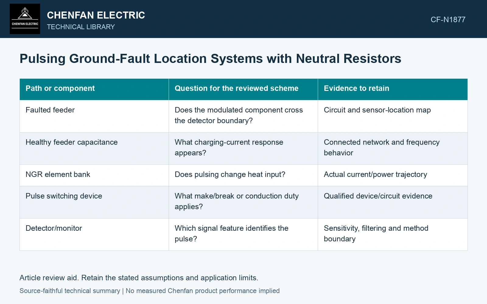
| Path or component | Question for the reviewed scheme | Evidence to retain |
|---|---|---|
| Faulted feeder | Does the modulated component cross the detector boundary? | Circuit and sensor-location map |
| Healthy feeder capacitance | What charging-current response appears? | Connected network and frequency behavior |
| NGR element bank | Does pulsing change heat input? | Actual current/power trajectory |
| Pulse switching device | What make/break or conduction duty applies? | Qualified device/circuit evidence |
| Detector/monitor | Which signal feature identifies the pulse? | Sensitivity, filtering and method boundary |
Make detection a signal question
The measured pulse should be interpreted relative to background current and the sensor’s frequency and time response. A healthy feeder can carry capacitive current during the faulted system state. It should not be assumed electrically silent merely because it has no resistive fault.
If the locator uses a particular modulation pattern, preserve the pattern and expected response in the verification record. An alarm or fluctuating reading does not by itself establish that the intended pulse crossed the observed boundary.
Calculate component duty from its waveform
Use the actual resistor power history to assess heating. A simple duty ratio may be useful only where the pulse magnitude and resistance are sufficiently constant and the thermal averaging is justified. For switches and contacts, current, voltage and repetitive action have their own qualified limits.
Healthy feeders can carry capacitive ground-current components during a fault. [2] Verify that the locator’s specified modulation and sensor response distinguish the intended changing component from that background at the actual feeder boundary.
Integrate the pulsing duty
Assume a 100 Ω element carries 5 A for 0.2 s and 3 A for 0.8 s in each 1 s cycle. Its energy is 1,220 J per cycle and average input is 1,220 W. Using the average current, 3.4 A, instead gives 1,156 W and understates heating. Qualify the actual waveform and switching hardware.
References
- IEEE, IEEE C57.32-2015, IEEE Standard for Requirements, Terminology, and Test Procedures for Neutral Grounding Devices (historical edition).
- T. Novak, J. Basar, J. Sottile and J. L. Kohler, The Effects of Cable Capacitance on Longwall Power Systems, IEEE Transactions on Industry Applications 40(5), 2004; DOI: 10.1109/TIA.2004.834025.