

A factory report lists an NGR resistance with several decimal places. The number needs a defined terminal boundary, temperature and uncertainty before it can be compared with the purchase specification. It may describe one element bank, the complete series assembly or a path that includes extra connections. [1]
The measuring method should fit the expected resistance and the decision being made. Greater display precision cannot compensate for an unidentified circuit path.
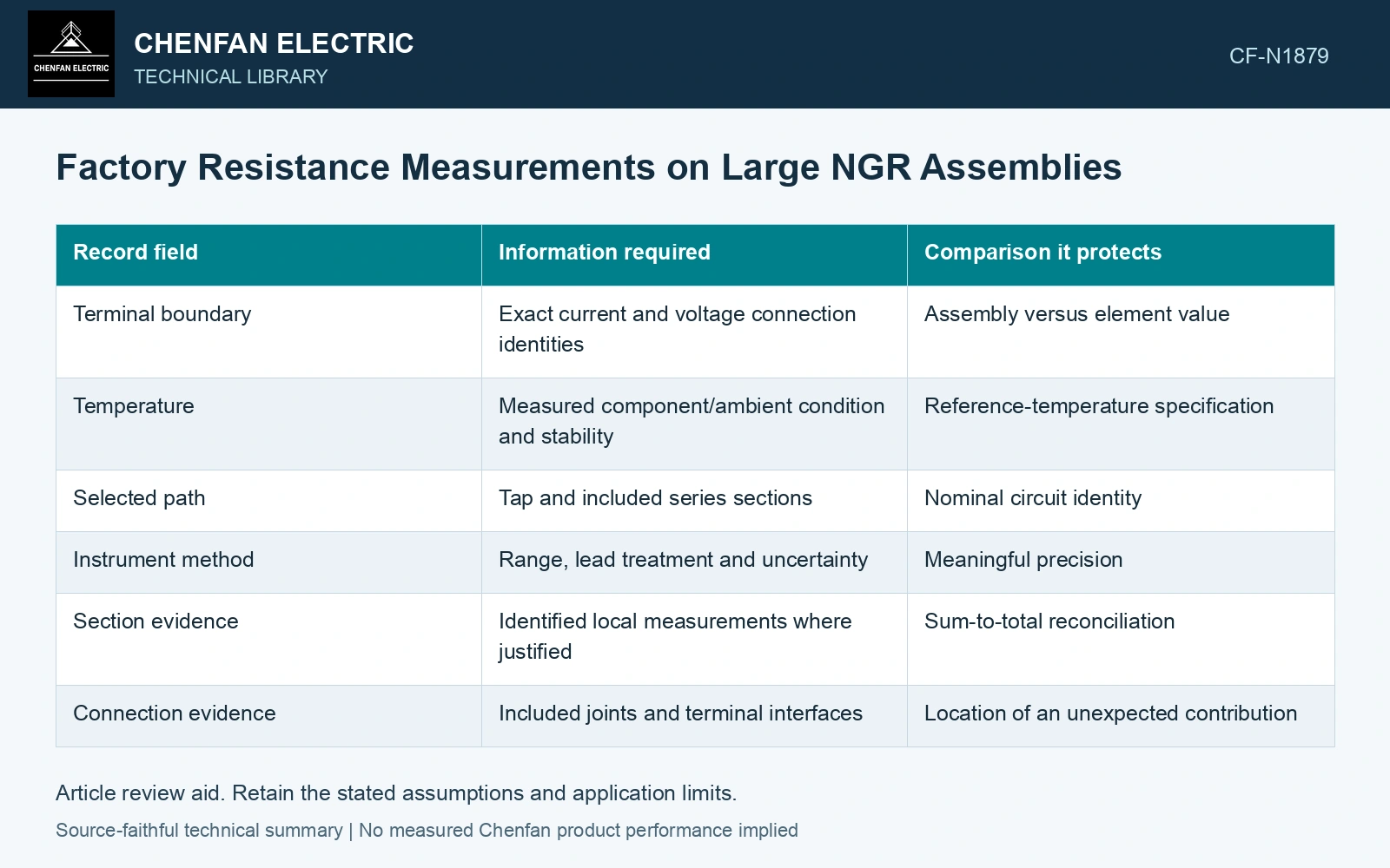
Define the measurement record
| Record field | Information required | Comparison it protects |
|---|---|---|
| Terminal boundary | Exact current and voltage connection identities | Assembly versus element value |
| Temperature | Measured component/ambient condition and stability | Reference-temperature specification |
| Selected path | Tap and included series sections | Nominal circuit identity |
| Instrument method | Range, lead treatment and uncertainty | Meaningful precision |
| Section evidence | Identified local measurements where justified | Sum-to-total reconciliation |
| Connection evidence | Included joints and terminal interfaces | Location of an unexpected contribution |
A two-terminal method can include lead and contact contributions in its result. A four-terminal arrangement separates current delivery from voltage sensing at defined points, but it still depends on correct endpoint placement and method suitability. It does not automatically remove every error or qualify a joint’s service behavior.
Use the actual material relationship
If the specification refers to another temperature, any conversion needs the element’s verified resistance-temperature relationship. Do not apply a copper winding formula to a nickel-chromium or stainless-steel element. The material and valid range should appear with the transformed value.
The elements may not be at one uniform temperature after another test. A single ambient reading is then an incomplete representation. Establish the applicable stabilization condition using the approved factory method rather than assuming the cabinet has cooled because its exterior feels cool.
Reconcile the section and assembly values
For a pure series path, compare the total with the sum of identified section and relevant connection contributions under comparable conditions. A disagreement can indicate an omitted path, changed temperature, measurement boundary or unintended branch. Investigate before labeling it an element defect.
Where tap branches or monitoring components remain connected, identify their effect. The assembled measuring network may not be the simple series resistor assumed by a spreadsheet.
Report measurement uncertainty with the reference-temperature resistance and terminal boundary. Combine identified uncertainty contributions with their sensitivity and correlation; extra displayed digits cannot replace that budget. [2]
Reconcile the measured terminal boundary
Assumptions: four series sections each measure 25.00 Ω at a uniform 20 °C, each with 0.020 Ω standard uncertainty; connections contribute 0.040 Ω with 0.010 Ω uncertainty. With uncorrelated inputs, expected total is 100.040 Ω with standard uncertainty √[4(0.020²)+0.010²] = 0.0412 Ω. An assumed assembly result of 100.800 Ω with 0.050 Ω standard uncertainty gives a 0.760 Ω discrepancy and combined uncertainty 0.0648 Ω. Using an assumed decision factor of 2 gives a discrepancy interval of 0.630–0.890 Ω, excluding zero. Hold reconciliation and verify temperature, taps, included connections and parallel monitor paths before releasing the report; this does not locate the defective element.
References
- IEEE, IEEE C57.32-2015, IEEE Standard for Requirements, Terminology, and Test Procedures for Neutral Grounding Devices (historical edition).
- B. N. Taylor and C. E. Kuyatt, NIST Technical Note 1297, Guidelines for Evaluating and Expressing the Uncertainty of NIST Measurement Results, 1994, sections 5 and 6.