

A pressboard edge radius changes the local electric field and the adjoining oil space. Keep the manufactured profile, locating tolerances and assembled oil interface together when preparing a field comparison. [1]
Calculation basis. Project-specific values and gates in the illustrative screens below are assumptions; cited catalogue values retain their source test conditions.
Compare actual profiles in their assembly context. Include the conductor shape, oil regions, board interfaces and locating tolerances. A radius specified on an isolated insulation drawing cannot describe that complete field problem.
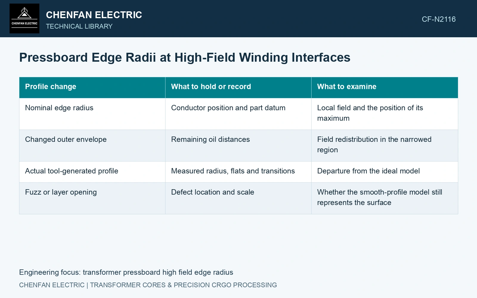
Keep the comparison geometry controlled
| Profile change | What to hold or record | What to examine |
|---|---|---|
| Nominal edge radius | Conductor position and part datum | Local field and the position of its maximum |
| Changed outer envelope | Remaining oil distances | Field redistribution in the narrowed region |
| Actual tool-generated profile | Measured radius, flats and transitions | Departure from the ideal model |
| Fuzz or layer opening | Defect location and scale | Whether the smooth-profile model still represents the surface |
Use suitable material properties and excitation for the duty being compared. A stationary dielectric field model with prescribed charge conditions is one model; long-duration conduction, surface charge accumulation and an impulse can require different treatment. Do not assume one contour plot qualifies all of them.
Assess the adjoining oil space and local field
An illustrative one-dimensional series-layer calculation shows the limitation. For a normal field with no free interface charge, displacement is continuous. The oil field is Eo = V/[εro(do/εro + db/εrb)], using consistent length units.
Take fictional values V = 10 kV, do = 2 mm, db = 3 mm, εro = 2 and εrb = 4. The oil field is 2.857 kV/mm. Replacing 0.5 mm of oil with board while keeping the total 5 mm gap gives do = 1.5 mm and db = 3.5 mm, and the oil field rises to 3.077 kV/mm.
This idealised calculation is not a winding-edge prediction or a withstand limit. It demonstrates that redistributing board and oil can change the stress carried by the remaining oil, so a geometry change needs more than a nominal-radius comparison.
Resolve the relevant curved interfaces in the numerical model and check mesh sensitivity at the location used for comparison. An ideal sharp corner can produce a mesh-dependent peak that cannot be interpreted as a measured physical field. Use an as-built profile or a defensible geometric bound rather than choosing a convenient sharpness.
Verify that the machining route delivers the modelled transition. A correct tool radius does not exclude a local flat, torn fiber fringe or separated layer. Inspect critical profiles and their cleanliness in the qualified final state.
Specify the manufacturable profile and locating tolerances with the interface’s electrical evidence. Retain the forming route’s supported radius range alongside the system assessment.
Compare oil stress after changing the board edge geometry
Series dielectric capacitances and conserved charge supply the stated planar screening relation [2]. Finished insulation acceptance must retain the actual winding-terminal dielectric boundary [3].
For the assumed planar series layers at 10 kV, relative permittivities 2 for oil and 4 for board, 2 mm oil plus 3 mm board gives oil field 2.857 kV/mm. Replacing 0.5 mm oil with board gives 3.077 kV/mm, a 7.69% increase. Resolve the curved edge and actual peak field before approving the radius change.
References
- IEC, IEC 60641-2:2004, Pressboard and presspaper for electrical purposes — Part 2: Methods of tests.
- U.S. Department of Energy, DOE-HDBK-1011/2-92, Electrical Science, Volume 2, 1992.
- IEC, IEC 60076-3:2013+AMD1:2018, Power transformers — Part 3: Insulation levels, dielectric tests and external clearances in air.