

Four-quadrant operation means a power conversion system can operate with either sign of active and reactive power within its permitted envelope. It does not mean that every combination of its separately advertised maxima is available. For transformer specification, convert the actual envelope into current cases at the relevant winding terminals, preserving voltage, duration and control restrictions.
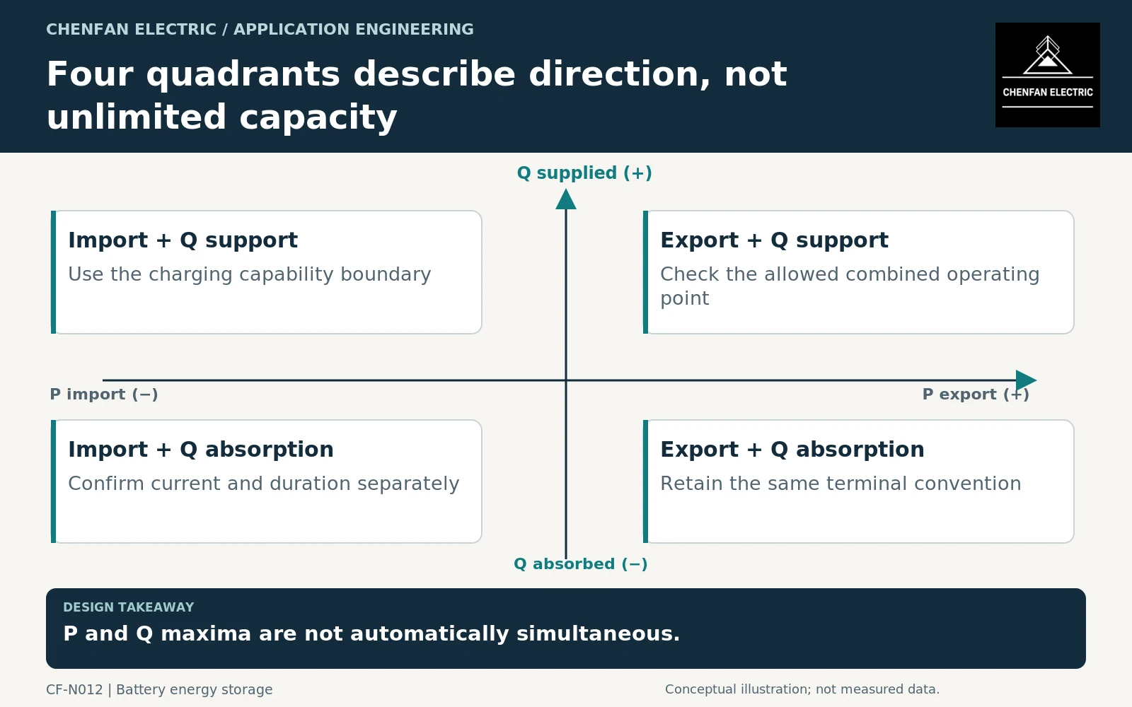
Read the envelope before selecting corner points
A rectangular list of maximum megawatts and maximum megavars can imply corner points that the converter cannot reach. The real capability boundary may be limited by current, temperature, direct current (DC) conditions or software. It may also differ between charging and discharging.
Request the guaranteed continuous envelope and any temporary extension separately. Identify whether a plotted boundary is a product capability, an installed setting or a plant-level permission. These can be three different limits.
Converter-transformer application guidance recognizes that the converter arrangement and its operating characteristics matter to the transformer interface. It does not replace the specific power conversion system (PCS) data required for this project. [1]
As a consistency check, an illustrative 5 MVA sinusoidal current envelope cannot simultaneously support 4 MW and 4 MVAr, because that combination requires approximately 5.66 MVA. The example illustrates geometry, not a universal circular capability curve for real converters.
Translate the boundary into winding current
For a balanced sinusoidal three-phase case, line current is I = √(P² + Q²)/(√3 × VLL). Use root-mean-square line-to-line voltage and quantities from the same electrical boundary. Lower terminal voltage can increase the current required for unchanged P and Q, unless the converter instead limits output.
The transformer assessment should therefore include the relevant voltage extremes rather than evaluating the envelope only at nominal voltage. Separate the converter’s current ceiling from the transformer’s allowable duty; one does not automatically certify the other.
Where harmonics materially contribute to current, the fundamental P-Q envelope is incomplete. Additional waveform information supports the nonsinusoidal-current assessment within the applicable equipment scope. [2]
Select cases that represent control priorities
A four-quadrant chart is a starting point, not an operating schedule. Identify how the controller chooses between active and reactive requests when it encounters a limit. Include mode changes and any grid-support state that can persist longer than a transient event.
| Control condition | Transformer case to retain |
|---|---|
| Active-power priority | Maximum allowed Q at the dispatched P |
| Reactive-power priority | Current at the required Q and permitted P |
| Low terminal voltage | Actual current-limited output boundary |
| Charging restriction | The available import-side envelope |
| Temporary support | Magnitude, duration and recovery assumptions |
Do not manufacture an impossible worst case by combining mutually exclusive controls. Conversely, do not rely on a normal dispatch setting when an enabled emergency mode can impose a different duty.
Preserve the assumptions through procurement
Issue a table of selected points with P, Q, voltage, current, duration and control mode. Reference the source envelope and its revision. The transformer supplier can then confirm which cases govern its design assessment and which require additional data.
General transformer application guidance supports matching ratings to operating conditions. Any subsequent thermal assessment must use the appropriate equipment model and chronological duty. [3]
The completed interface document should also specify change control. Updating converter firmware, enabling a new grid-support mode or changing a plant current limit can alter the usable envelope without changing the hardware nameplate. Rechecking that change is more defensible than assuming the words “four quadrant” permanently describe every permissible transformer duty.
Core procurement checkpoint: Carry the full operating envelope into design approval
A four-quadrant capability plot is an input to transformer design, not a manufacturing drawing for a core. Ask the responsible designer to identify which voltage and frequency conditions govern the core and which P-Q cases govern winding current. Keep those decisions in the approval record so that later converter-control changes trigger a deliberate review instead of an undocumented material substitution.
For the core enquiry: Approved voltage-frequency envelope; drawing and material revision; converter change-control reference; core inspection and test boundary.