

A grid-forming battery system requires a transformer specification coordinated with the island it may energize and support. The transformer must be represented in the voltage-frequency, grounding, excitation and transition studies. A conventional megawatt rating does not establish whether the converter can energize the transformer, sustain its magnetizing demand or respond to island load changes within its current limits.
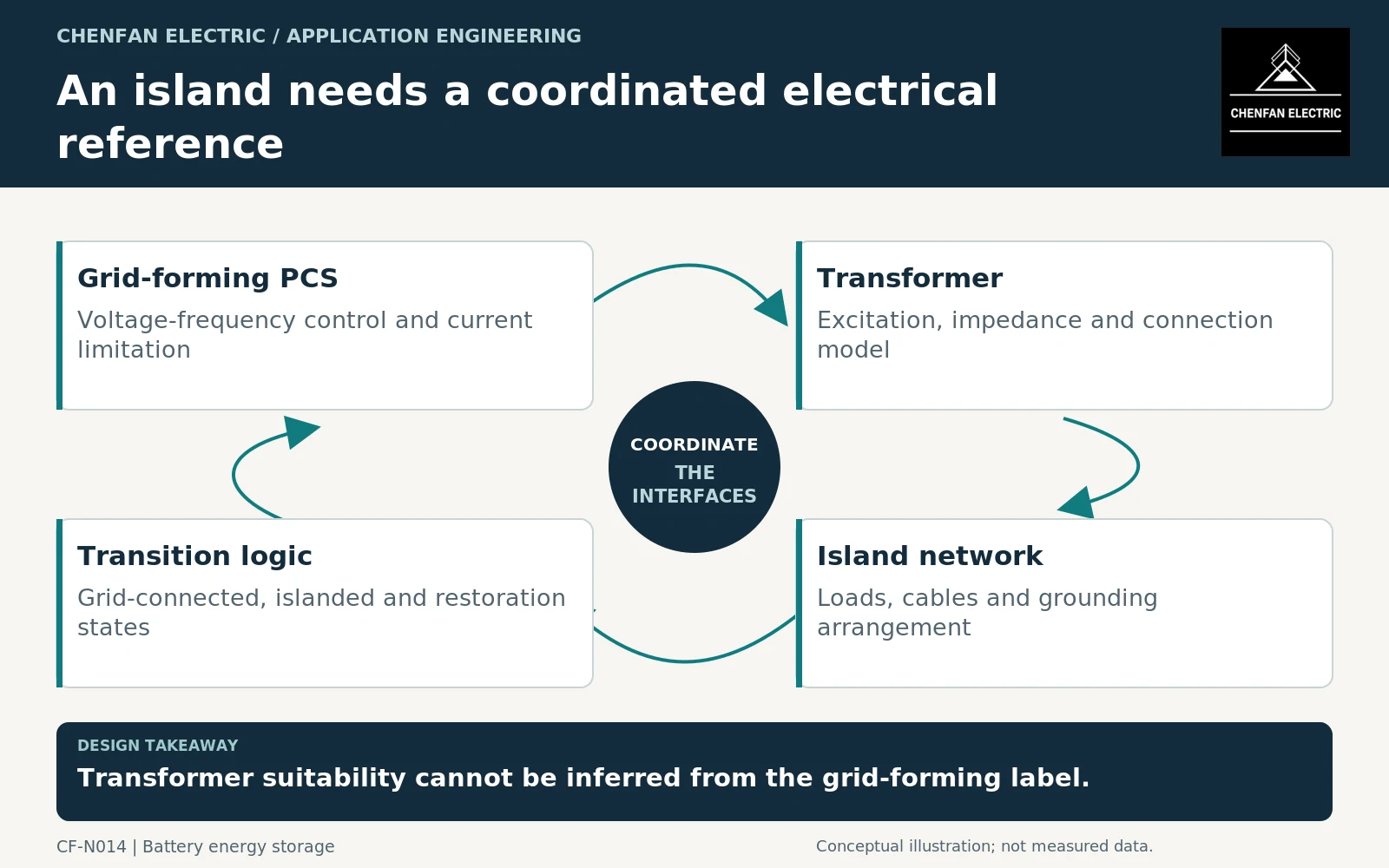
Distinguish grid-forming control from transformer capability
Grid-forming describes converter control behavior, not a transformer certification. Research roadmaps treat it as a system-level topic involving controls, protection, modeling and interactions. The transformer remains one component whose characteristics influence that system. [1]
State the intended modes: grid connected, an already energized island, dead-bus energization, resynchronization or restoration of selected loads. Capability in one mode does not prove capability in all of them. A system that maintains an established island may still require a separate transformer-energization strategy.
Provide the converter’s current-limiting behavior and relevant voltage-frequency limits. A controller may reduce voltage, limit current or change its response during a disturbance. These actions affect the transformer and connected loads differently from a stiff utility source.
Supply a model suitable for the question
The study requires winding connections, impedance data on defined bases, no-load characteristics and the excitation model needed for the intended analysis. A steady-state load-flow model alone cannot represent every energization or control interaction.
For voltage-frequency assessment, distinguish steady operating conditions from transient waveforms. The familiar relationship between voltage, frequency and flux is useful under its waveform assumptions, but it should not be applied mechanically to a distorted or rapidly changing startup trajectory. Transformer energization involves additional factors such as residual flux and switching conditions. CIGRE’s study-guide summary identifies energization as a system phenomenon capable of producing voltage dips and temporary overvoltages. [2]
Ask the model owner to identify parameter sources, validation limits and unsupported operating regions. A visually convincing simulation is not evidence when its saturation or current-limit assumptions are arbitrary.
Define the island’s grounding and load boundaries
The transformer connection and neutral arrangement help determine how the island behaves during unbalanced operation and earth faults. Document the intended grounding arrangement in each mode, including transitions when a utility connection is removed or restored. This is an engineered protection and earthing task, not a generic wiring recommendation.
| Island input | Required agreement |
|---|---|
| Grounding reference | Which source or device establishes it in each mode? |
| Load pickup | Which load blocks and starting events are permitted? |
| Converter limitation | What voltage and current behavior occurs at the limit? |
| Transformer excitation | Which model and initial-state assumptions apply? |
| Transition sequence | Which connections remain energized during the change? |
Large motors, rectifier loads and cables should appear in the model at an appropriate level of detail. An island judged stable with a simple resistive load is not thereby validated for the site’s actual load mix.
Separate three acceptance claims
First, the transformer supplier should confirm the equipment against the agreed electrical and environmental duty. Second, the converter supplier should confirm its permitted operating modes and relevant control models. Third, the system integrator should demonstrate the coordinated operating cases using an agreed study and test plan.
General transformer application guidance remains relevant to connections and operating conditions, but it cannot certify the complete islanding scheme. [3] Any restrictions on load pickup, operating voltage or supported configuration should remain visible in the handover rather than disappearing into a model report.
The deliverable is a coherent interface package: single-line diagrams for each mode, current-limit data, transformer model, grounding philosophy and transition cases. That package provides a defensible basis for island operation. The phrase “grid-forming compatible,” without those boundaries, does not.
Core procurement checkpoint: Keep islanded excitation assumptions visible
For a grid-forming installation, the transformer manufacturer should identify the voltage and frequency operating range used in the magnetic design and the data required by the system model. A core supplier may provide agreed manufacturing or test records, but these are not proof of stable islanded operation. Do not equate a standard-frequency core-loss check with validation of the converter’s control response.
For the core enquiry: Designer-approved excitation envelope; core geometry; requested model-data responsibility; agreed test conditions and deliverable records.