

A closed-loop cooling specification for an offshore wind transformer must define the complete thermal interface, not just identify a heat exchanger. The transformer, circulation equipment, heat rejection system and platform utilities must use compatible operating assumptions. A mismatch in inlet temperature, available flow or failure response can invalidate an otherwise reasonable equipment selection.
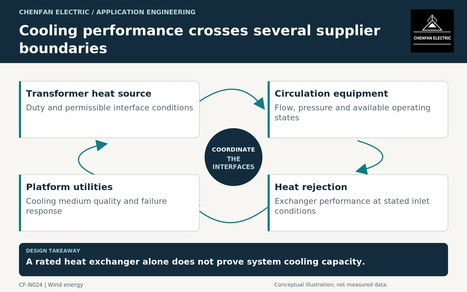
Draw the heat path and name every medium
Identify which medium contacts the transformer, which medium circulates through the intermediate circuit and where heat is ultimately rejected. Do not use the word “water-cooled” without explaining the actual arrangement. Dry-type air-to-water cooling and an insulating-liquid-to-water exchanger are different systems.
IEC 60076-22-4 addresses insulating-liquid-to-water heat exchangers within its scope. It should not be cited as though it covers every air cooler, seawater circuit or dry-type enclosure. [1]
The interface drawing should identify supply and return connections, measurement locations and the owner of each circuit. It is a functional diagram, not a fabrication or piping instruction.
Specify inlet conditions rather than nominal capacity alone
The transformer’s cooling assessment should use agreed inlet temperatures, flow conditions and available cooling stages. The heat-rejection supplier needs the corresponding heat duty and return conditions. Both sides should identify the operating case that governs their guarantee.
A cooler advertised with a heat-transfer capacity has achieved that value only under some stated conditions. Changing the inlet temperatures or medium properties changes the system problem. Ask for the applicable performance basis rather than treating the number as independent of its conditions.
For liquid-immersed transformers, IEC 60076-2 addresses temperature rise within its stated equipment and test scope. It should not be used as a general temperature-rise reference for dry-type transformers; their applicable framework must be selected separately. The surrounding platform system must provide the boundary conditions assumed in the equipment assessment. [2]
Include failures and unavailable equipment
| Condition | Interface question |
|---|---|
| Normal operation | Which pumps and exchangers are required? |
| One cooling component unavailable | Is output reduced, or is another stage available? |
| High cooling-medium temperature | Which operating limit is approached? |
| Loss of circulation | Which detection and coordinated response apply? |
| Suspected leakage | Who identifies, isolates and assesses the affected boundary? |
The cited pump and fan standards address specified components of liquid-immersed power transformers and reactors, not a generic dry-type cooling circuit. They do not establish the redundancy of an entire offshore cooling installation. [3] [4]
Specify the intended response through the responsible control and protection design. This article does not define trip settings or an emergency operating procedure. The purchasing requirement is that the response and responsibility are explicit before the system is built.
Preserve access and maintainability
Cooling equipment needs inspection, cleaning and replacement access. Identify removable components, service connections and any work that requires the transformer or shared platform cooling system to be unavailable. A nominally redundant pump arrangement may offer little maintenance benefit if both pumps share an inaccessible isolation boundary.
The handover package should contain a heat-balance basis, interface schedule, component duties, instrumentation list and failure-state matrix. Confirm that transformer and platform documentation use the same medium names, temperature reference points and flow conventions.
The most important guarantee is not an isolated cooler capacity. It is that the combined system provides the specified transformer inlet conditions throughout the agreed operating states, with clear restrictions and responses when those conditions cannot be maintained.
Core procurement checkpoint: Make the cooling boundary visible at the core handoff
The core supplier should receive the final assembly interfaces affected by the cooling arrangement, including any specified clearances, supports or supplied clamps. Air-cooled dry-type and liquid-immersed designs must not inherit one another’s accessory-standard claims. The transformer and platform designers remain responsible for cooling-loop performance; the core order should state only the geometry, material and components actually included.
For the core enquiry: Transformer construction type; approved core and clamp interface; cooling-related keep-clear zones; supplied component and test boundaries.