

Several power conversion system (PCS) units can share a transformer, but the specification must distinguish a common low-voltage bus from separate converter windings. The current-sharing and isolation questions differ between those arrangements. A total plant megawatt limit is not enough: define individual branch limits, simultaneous operation, control ownership and the conditions that remain possible when a PCS is unavailable.
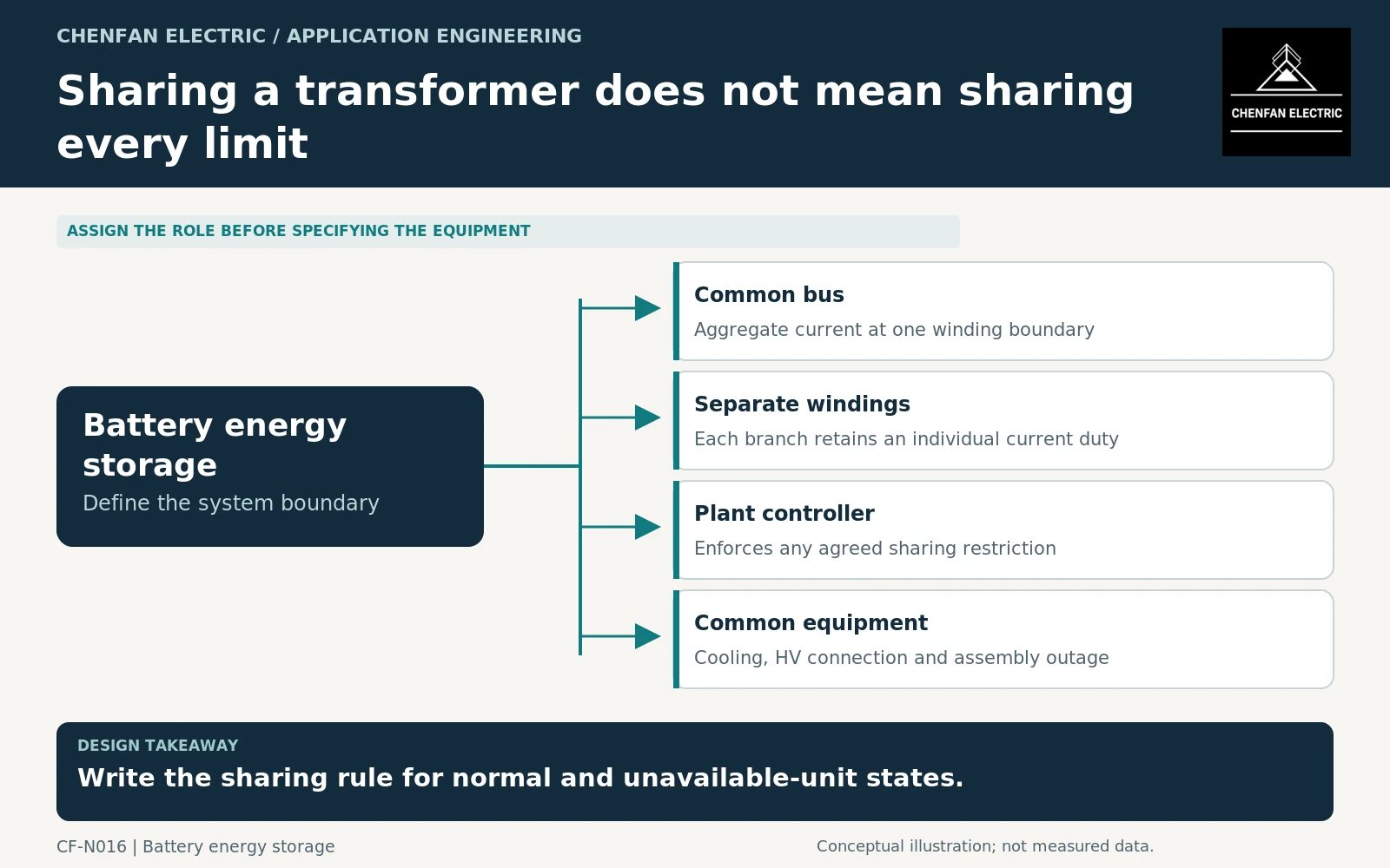
Identify the electrical sharing boundary
On a common bus, the transformer winding sees the net current resulting from connected converters and local loads. Individual converters can still have different currents and reactive-power contributions. With separate windings, each winding must be assessed independently as well as within the transformer’s permitted combined duty.
A multiwinding configuration also needs suitable pairwise-impedance information and connection data for system studies. Do not represent it as several completely independent transformers merely because it has separate terminals.
Transformer application guidance addresses connections, ratings and parallel-operation considerations. Converter-transformer application guidance becomes relevant where the arrangement introduces converter-specific requirements. [1] [2]
State what controls the combined current
Determine whether the limit is enforced locally by each PCS, centrally by a plant controller, or by a coordinated combination. Identify the measurement point and the response when communication is lost. A software-based sharing assumption must not remain invisible in a transformer rating calculation.
Review active and reactive power together. Two converters with limited active export may still impose substantial combined reactive current. If their commands differ, distinguish net current at the transformer from currents circulating through local branches.
The specification need not prescribe a universal sharing algorithm. It should require an agreed control description, defined limits and evidence that the permitted operating envelope remains within the equipment assumptions.
Include isolation and degraded configurations
| Configuration | Question to close |
|---|---|
| All PCS units available | What simultaneous current envelope is allowed? |
| One PCS disconnected | Can remaining units increase output? |
| One winding out of service | Which common components remain energized? |
| Communication unavailable | What limits apply without central dispatch? |
| Planned maintenance | Which isolation boundaries are physically available? |
A PCS outage does not automatically make its winding safe to access. Other sources and the transformer’s shared magnetic system must be considered through the approved isolation and protection design. This is a boundary-definition issue, not an instruction to perform switching or maintenance.
Similarly, a transformer outage can remove all connected PCS units regardless of their individual redundancy. Include the common high-voltage connection, cooling systems and auxiliary supplies when assessing availability.
Freeze the permitted combinations in the contract
Provide a matrix linking each operating configuration to winding currents, duration and control assumptions. The supplier should identify which combinations have been assessed and which are prohibited or conditional. Keep this matrix aligned with the plant controller specification.
Where loading varies over time, use the appropriate thermal assessment rather than assuming that a shared nameplate total guarantees every duty cycle. Mineral-oil loading guidance addresses loading and ambient effects within its scope. [3]
Acceptance should include consistency between the approved single-line diagram, converter configuration, transformer winding schedule and implemented sharing limits. A later PCS expansion or firmware change should trigger review when it changes that envelope.
The result is not merely a transformer “for four PCS units.” It is a defined operating agreement explaining which units can operate together, how their currents are bounded and what service remains when a branch or common component is unavailable.
Core procurement checkpoint: Use an unambiguous core-to-winding interface
Several PCS units sharing a transformer can lead to more than one winding arrangement. The core supplier needs the chosen limb and window geometry, not an informal sketch showing only converter totals. Freeze the assembly sequence and delivery form, especially where pre-stacked packets will be opened for winding insertion. Electrical isolation and unequal loading remain matters for the complete-transformer design.
For the core enquiry: Approved coil-envelope interface; limb and window dimensions; joint and packet sequence; assembly state at delivery.