

A valve short circuit can create a current combination unlike a conventional AC terminal short circuit. Which windings participate depends on the valve, bridge connection and other conducting paths. Local axial forces require that combination to be mapped into the actual winding geometry. Apply the HVDC transformer specification framework of IEC/IEEE 60076-57-129 to the stated liquid-immersed equipment [1].
Start with the faulted valve ID and the pre-fault operating state. Include the AC source, bridge groups, DC circuit and clearing sequence. Solve the currents in all transformer windings on a consistent reference base rather than applying one terminal current to every coil.
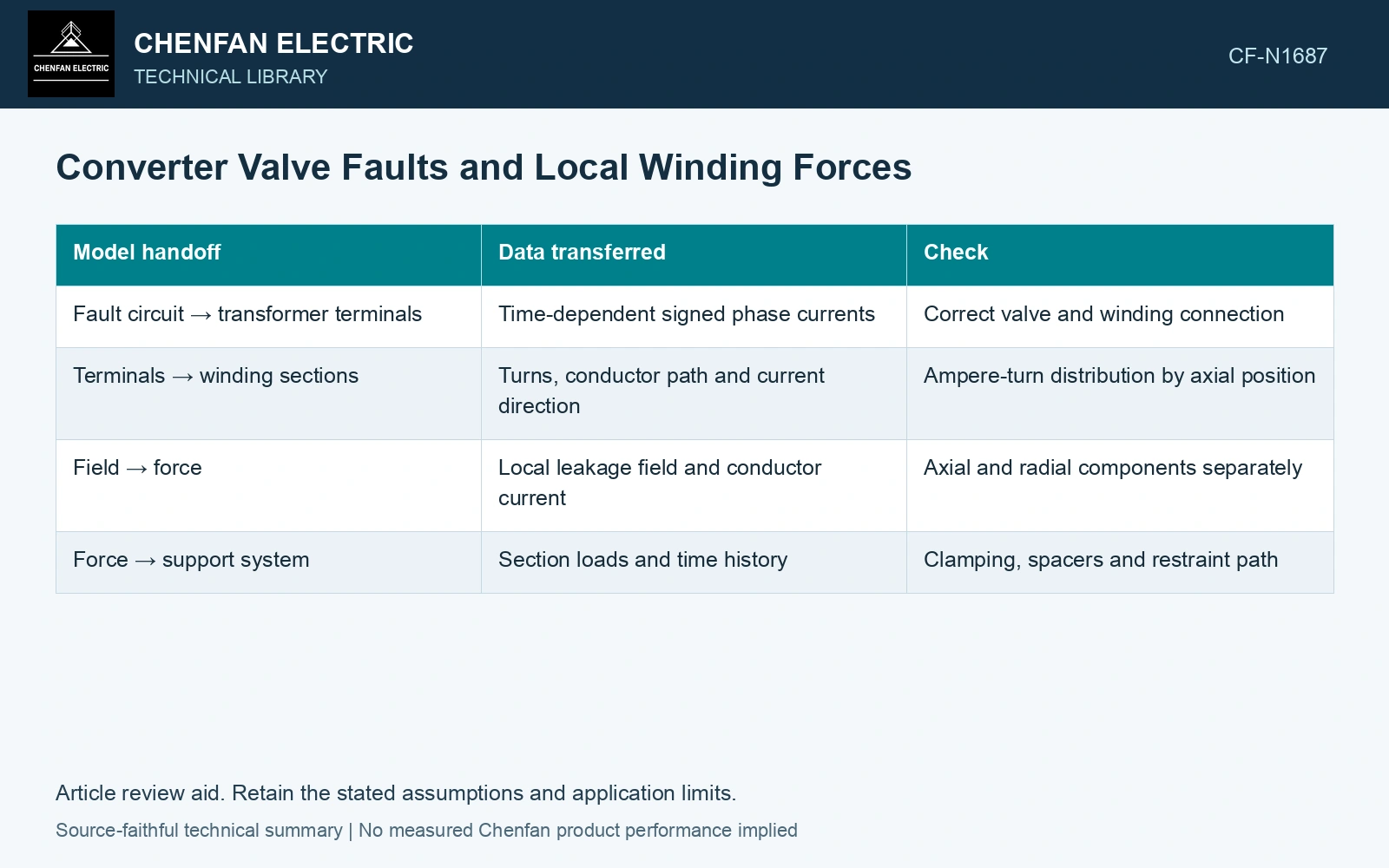
Connect circuit and mechanical models
| Model handoff | Data transferred | Check |
|---|---|---|
| Fault circuit → transformer terminals | Time-dependent signed phase currents | Correct valve and winding connection |
| Terminals → winding sections | Turns, conductor path and current direction | Ampere-turn distribution by axial position |
| Field → force | Local leakage field and conductor current | Axial and radial components separately |
| Force → support system | Section loads and time history | Clamping, spacers and restraint path |
Why total ampere-turn balance is insufficient
A transformer can have an approximately balanced total ampere-turn sum while the axial distributions differ locally. That spatial mismatch creates leakage fields and forces within sections. A whole-winding sum therefore cannot establish local mechanical adequacy.
In a fixed linear geometry, forces often scale approximately with current squared. Use that only as a screening comparison. Different winding current ratios alter the field distribution; saturation and conductor displacement can invalidate simple rescaling of a previous force result.
Use current scaling only for an unchanged force pattern
Assume two fault cases with the same winding-current ratios and linear geometry, but peak current rising from 20 kA to 24 kA. The screening force multiplier is (24/20)² = 1.44. An assumed original section force of 100 kN becomes 144 kN, exceeding an assumed section screening capacity of 130 kN by 14 kN. Escalate that section for mechanical review. If valve location changes the winding-current combination, discard this multiplier and solve the new force distribution.
Review the fault sequence as a family of cases
Compare fault locations that change the current combination, including the relevant bridge group and fault inception conditions. Keep the peak phase current and the instant used for the force calculation aligned. Independently maximizing every winding current can create a physically impossible combination.
The governing mechanical case is the current distribution that loads the weakest restraint path, with its initial load and clearing action specified. If valve or control behavior remains uncertain, the calculated force remains conditional. A generic short-circuit rating cannot resolve that missing current history.
Include normal converter operation and converter-side faults in the transformer transient study [2].
References
- IEC/IEEE, IEC/IEEE 60076-57-129:2017, Power transformers – Part 57-129: Transformers for HVDC applications.
- CIGRE WG B4.51, Technical Brochure 609, Study of Converter Transients Imposed on the HVDC Converter Transformers, 2015.