

A height-constrained transformer core should be redesigned with the whole active part, not shortened by reducing yoke section in isolation. The available height must accommodate magnetic area, winding insulation, cooling and structural functions. A lower outline can require greater width, different winding proportions or another magnetic topology.
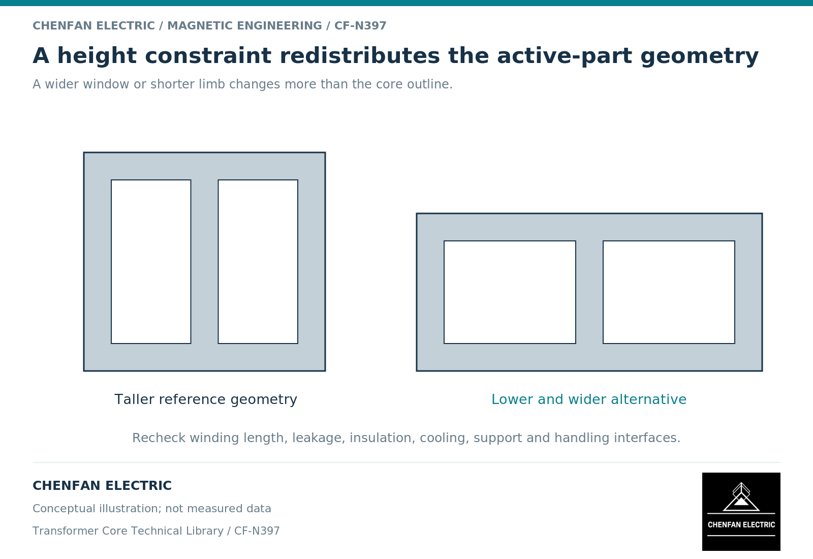
Allocate the height before changing steel dimensions
Separate overall transport height from tank height, active-part height, winding height, end clearances and core-yoke dimensions. The controlling limit may sit outside the core itself.
A magnetic equivalent-circuit description links limb and yoke geometry to their branch behavior and shared return paths. [1] Reducing a yoke’s section while retaining its flux raises average flux density; it does not merely reduce unused material.
Likewise, reducing window height can constrain winding height or electrical clearances. The first useful drawing is therefore a dimension budget showing where height is consumed and which constraints are fixed.
Compare complete geometric alternatives
Possible design variables include wider or differently stepped magnetic sections, altered window proportions, revised winding dimensions and alternative core arrangements. Their suitability depends on the electrical duty and available manufacturing methods.
Transformer design guidance treats core size, winding mean turn length, turns and window allocation together. [2] A wider core can increase conductor path length or tank width, while a shorter winding can change leakage behavior and end-field exposure.
| Candidate change | Coupled consequence to assess |
|---|---|
| Lower yoke dimension | Net section and local magnetic operating point |
| Wider magnetic section | Winding circumference and transport width |
| Shorter winding | Leakage field, cooling and dielectric end regions |
| Wider window | Active-part width and structural support |
| Different topology | Flux paths, winding arrangement and assembly method |
A candidate should not be credited with a height reduction while its required clearances are omitted from the drawing.
Keep the comparison on one duty basis
Retain induced voltage, frequency, tap envelope, loss obligations and insulation requirements unless the project explicitly permits them to change. Compare complete masses and dimensions, not only the core mass.
If an alternative uses fewer turns, recalculate its magnetic excursion and winding consequences. If it uses a different net area, preserve the correct area definition. If it changes winding shape, revisit mean turn length and local field exposure.
A reduced-height concept is not a validated design simply because a three-dimensional model fits inside the envelope. Geometric fit proves only the geometry represented by that model.
Release the constraint and the chosen trade-off
The final design note should identify the original height limit, the dimensions that were fixed, the variables changed and the checks supporting the selected arrangement. Record any increase in width, mass, conductor quantity or assembly complexity rather than hiding it as a secondary detail.
For core manufacturing, the released section schedule, window dimensions, joints and reference datums must correspond to the approved active-part revision. A verbal request to “make it lower” is not a complete change instruction.
The responsible transformer designer retains the dielectric, thermal and mechanical integration. The core supplier implements the agreed magnetic structure and flags manufacturing constraints before release.
The useful result is a balanced active-part design that satisfies the height boundary without silently consuming another margin. Shortening one steel dimension is an input to that review, not the conclusion.
References
[1] Manitoba Hydro International / PSCAD. The UMEC Approach.
[2] Lloyd Dixon / Texas Instruments. Magnetics Design 4 – Power Transformer Design.