

Split-winding transformers can share a main magnetic structure while their secondary sections carry unequal duties. The shared core does not make the sections equivalent to two independent transformers, and unequal secondary loading does not automatically create independent main fluxes. The designer must distinguish mutual excitation from the spatial leakage fields produced by each loading combination.
Preserve the common-flux relationship
In an idealized coupled transformer, the induced voltage in each winding follows its turns and linked main-flux change. The primary current adjusts to balance the secondary ampere-turn demand, subject to excitation and nonideal effects. [1]
Splitting a secondary changes its electrical and spatial arrangement. It does not by itself allocate a separate main-core flux to each section according to its share of output power.
Actual terminal voltages can differ because winding resistance, leakage impedance, connections and regulation differ. Keep those terminal effects separate from the common induced-voltage relationship.
Describe where each section is located
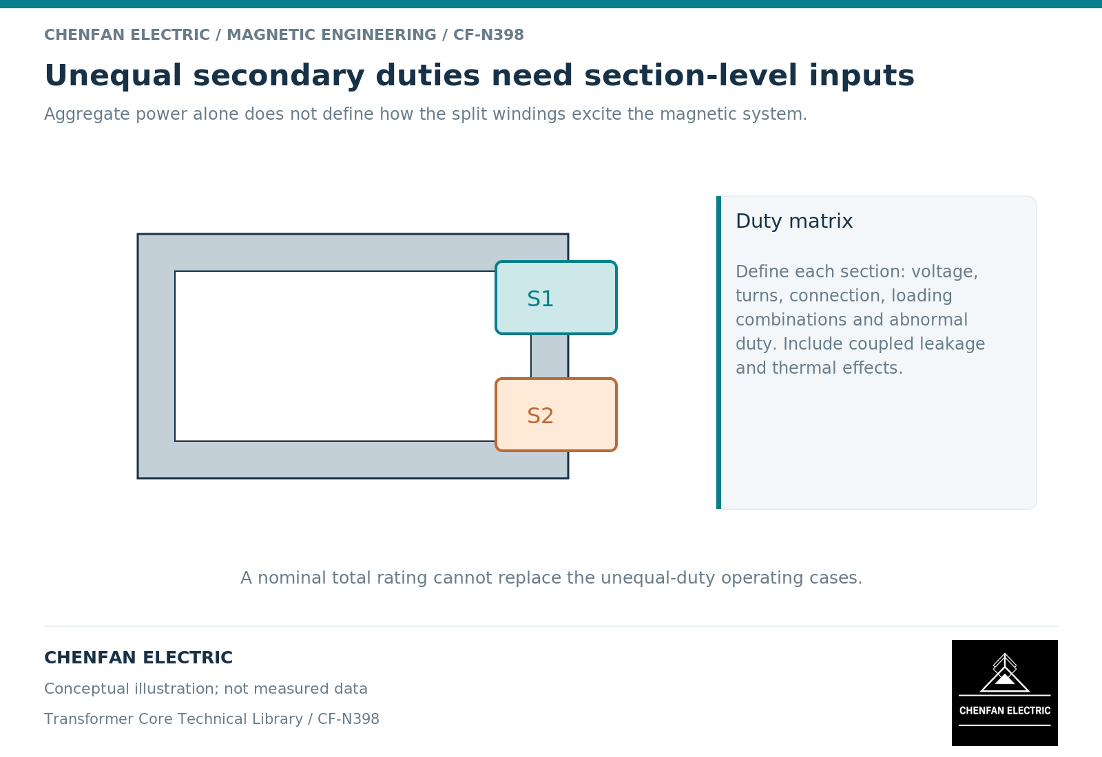
A split arrangement may place sections at different axial or radial locations. Equal total ampere-turns can then have different local cancellation patterns, especially under unequal loading.
Magnetic models require correct winding-to-core mapping and coupling. [2] A circuit model with two secondary labels is not sufficient for a local field review unless the associated geometry is represented or justified through equivalent parameters.
Identify the turns, polarity, physical location, connection and allowed loading of each section. Include lead routes when they influence surrounding structures. The word “split” does not specify whether the arrangement is axial, radial or another construction.
Evaluate a loading matrix rather than one total rating
| Operating case | Question to examine |
|---|---|
| Both sections at their defined duty | Combined thermal and leakage behavior |
| One section heavily loaded, the other light | Local ampere-turn distribution and regulation |
| One section unloaded | Remaining section’s field and voltage behavior |
| Unequal harmonic content | Current waveform and structural exposure |
| Relevant fault or exceptional case | Equipment-specific mechanical and thermal duty |
The permitted combinations come from the system and transformer design. Do not assume that any loading split is acceptable merely because the sum of apparent powers remains below one nameplate value.
The most demanding case can differ by observable. One case may govern winding temperature, another local clamp exposure, and another regulation or impedance performance.
Hand over the core duty without losing the winding context
The core supplier needs the controlled magnetic topology, net areas and excitation envelope. The transformer original equipment manufacturer retains the loading matrix, winding geometry and complete leakage, thermal, dielectric and mechanical assessment.
A revision that redistributes secondary turns or changes section position may leave the core unchanged while requiring a new active-part field review. Preserve this distinction in change control rather than either reopening every core dimension or declaring the system unaffected.
A useful report shows the common magnetic excitation separately from the current-driven field cases. It identifies which conclusions apply to all loading combinations and which apply only to specific ones.
That separation prevents two opposite mistakes: treating each secondary as though it owns an independent core, and assuming that shared main flux makes unequal secondary duties electromagnetically unimportant. The core can remain common while the surrounding field and heating change substantially.
References
[1] Lloyd Dixon / Texas Instruments. Magnetics Design 4 – Power Transformer Design.
[2] Manitoba Hydro International / PSCAD. The UMEC Approach.