

Unbalanced station auxiliaries can introduce negative-sequence current into a generator-transformer unit. The generator rotor and the transformer do not respond to it in the same way. A machine negative-sequence limit cannot serve as a transformer thermal limit, and a satisfactory transformer load does not prove the generator is within its capability. Separate positive-, negative- and zero-sequence quantities on the actual winding connection [1].
Calculate sequence components at each relevant terminal from simultaneous phase phasors. With a = exp(j120°), one common convention gives I2 = (Ia + a²Ib + aIc)/3. Confirm phase labels and the convention used by the instrument; swapping phases can interchange positive- and negative-sequence reporting.
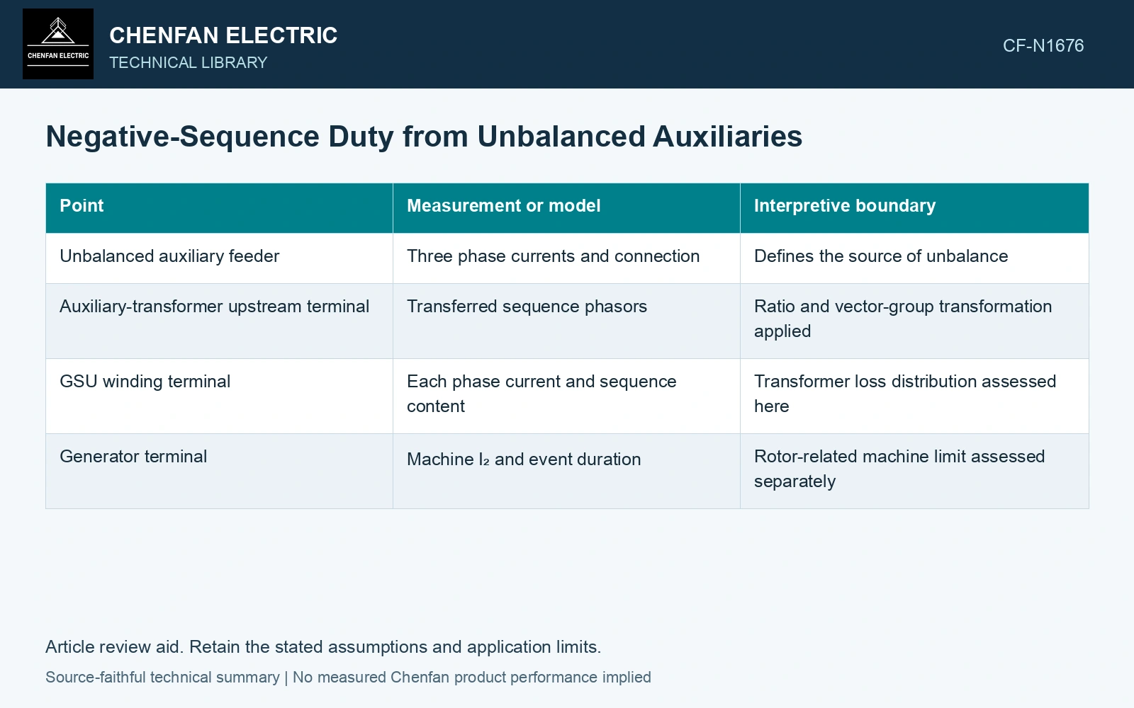
Trace the source through the winding connection
| Point | Measurement or model | Interpretive boundary |
|---|---|---|
| Unbalanced auxiliary feeder | Three phase currents and connection | Defines the source of unbalance |
| Auxiliary-transformer upstream terminal | Transferred sequence phasors | Ratio and vector-group transformation applied |
| GSU winding terminal | Each phase current and sequence content | Transformer loss distribution assessed here |
| Generator terminal | Machine I₂ and event duration | Rotor-related machine limit assessed separately |
Positive and negative sequences can transfer through transformer connections with corresponding phase shifts. Zero sequence is a different case whose transfer depends strongly on delta paths and grounding. A delta that blocks external zero-sequence transfer does not generally eliminate negative sequence.
Compare the same unbalance percentage at different loads
Assume balanced positive-sequence reference currents of 100 A and 1000 A, each with negative sequence equal to 5% of positive sequence for 10 s. Negative-sequence currents are 5 A and 50 A. Their I₂²t values are 250 A²s and 25,000 A²s, differing by a factor of 100 despite the same reported percentage. Use absolute sequence currents and duration in the machine study, while deriving the transformer loss and phase-current duty separately. The ratio by itself cannot define either equipment limit.
Do not reduce the duty to one percentage
The ratio I2/I1 is useful for comparing unbalance, but absolute current and duration are also required. The same percentage at a small load and near rated load means different negative-sequence amperes. Individual phase currents may reveal a winding carrying the highest RMS duty even when the three-phase apparent power looks moderate.
For generator assessment, use the manufacturer’s applicable negative-sequence capability and the protection study. For the transformer, assess phase heating, stray loss and any relevant structural duty using its design. Avoid carrying a generator I₂²t criterion directly into a transformer specification.
A practical load review should identify whether the unbalance is continuous, a starting event or a feeder fault. Correcting phase allocation may remove a continuous source; protection and switching govern fault duration. Keeping these causes separate prevents a brief fault waveform from being mistaken for the normal auxiliary operating envelope.
For mineral-oil equipment, relate the loading assessment to operating temperature and thermal ageing [2].
References
- Amberg, A., and Rangel, A., Tutorial on Symmetrical Components, Part 2: Answer Key, Schweitzer Engineering Laboratories, revision 20201019, 2020, Sections I and III.
- IEC, IEC 60076-7:2018, Power transformers – Part 7: Loading guide for mineral-oil-immersed power transformers.