

A synchronizing error creates a voltage difference between the generator and the system at closing. Its current distribution follows the network and the multiwinding transformer’s impedance relationships. There is no universal percentage of the main current that can be assigned to the tertiary. Keep the selected winding arrangement within the general power-transformer specification framework [1].
Represent the closing mismatch as ΔV = Vg − Vs with both phasors referred to the same side and phase sequence. Even equal voltage magnitudes create a mismatch when the phase angles differ. For equal magnitude V and angle difference δ, |ΔV| = 2V|sin(δ/2)|. Here V is phase RMS voltage and δ is the electrical angle.
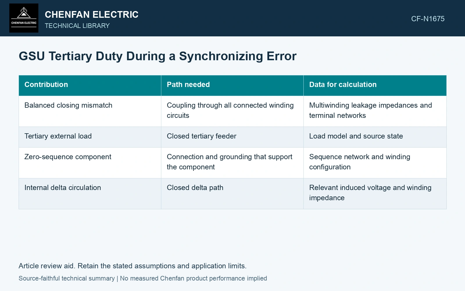
List what can actually drive the tertiary
| Contribution | Path needed | Data for calculation |
|---|---|---|
| Balanced closing mismatch | Coupling through all connected winding circuits | Multiwinding leakage impedances and terminal networks |
| Tertiary external load | Closed tertiary feeder | Load model and source state |
| Zero-sequence component | Connection and grounding that support the component | Sequence network and winding configuration |
| Internal delta circulation | Closed delta path | Relevant induced voltage and winding impedance |
A balanced fundamental-frequency mismatch should not automatically be labelled a zero-sequence event. Zero sequence requires its own source and return path. Conversely, a closed delta can carry internal circulating current that is absent from its external line-current measurement.
Use the right transformer model
A two-winding equivalent can show the main mismatch current but cannot reliably partition a three-winding event. Obtain the winding-pair impedances, connection and terminal load states. Use a consistent reference base and check whether the derived equivalent represents the supplied impedance data.
The formula for ΔV is a screening relation. Current peaks also depend on closing instant, resistance, network dynamics and saturation. A mechanical-duty calculation needs phase-current peaks and spatial force distribution rather than only the mismatch’s RMS magnitude.
Screen the closing mismatch on one voltage base
Assume equal 10 kV phase-RMS sources with 10° closing-angle mismatch and total series reactance 2 Ω at 50 Hz. Mismatch voltage is 2 × 10 × sin 5° = 1.743 kV; the simple symmetrical current estimate is 1743/2 = 872 A. At 5° mismatch it is 436 A, about half. These values only screen the main path. Use the three-winding network to allocate tertiary duty and a transient model for peaks; the screen does not establish a permitted synchronizing angle.
Preserve the error case without endorsing it
Define voltage difference, angle error, slip frequency and breaker closing scatter as study inputs. Record tertiary load and earthing in the same case file. Compare its current and thermal burden with the tertiary’s actual design data.
The review should distinguish protection prevention of an erroneous close from the equipment’s specified withstand case. Calculating the latter is not permission to synchronize outside the plant’s approved conditions.
Verify the selected terminal ratio with a test method matched to the winding connection [2].
References
- IEC, IEC 60076-1:2011, Power transformers – Part 1: General.
- Ohlen, M., and Werelius, P., A Guide to Transformer Ratio Measurements, Megger Sweden, 2010-01-18, Definitions and TTR measurements.