

Laser-track start and stop zones have their own power and motion history. Qualify those transition spans separately from the steady middle section to establish the usable treated width of the strip.
Draw the endpoint zones in material coordinates
Locate the physical strip edges, the intended treatment endpoints and the actual beam-enable and beam-disable positions. Add the portions of the path where scanner speed is changing. Keep the start and stop separate: control delay, motion direction and the preceding thermal history may differ.
For steady continuous-wave motion, incident energy per path length can be described by power divided by relative speed, in J/m. That expression does not describe a stationary endpoint by substituting zero speed. During a dwell or transition, energy follows the actual power-time history and its distribution over the moving or stationary spot. A nominal scan speed cannot resolve it.
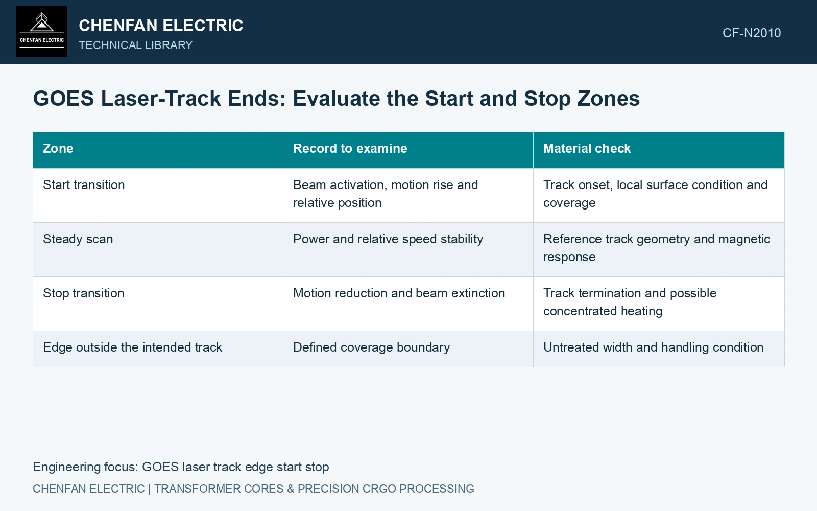
| Zone | Record to examine | Material check |
|---|---|---|
| Start transition | Beam activation, motion rise and relative position | Track onset, local surface condition and coverage |
| Steady scan | Power and relative speed stability | Reference track geometry and magnetic response |
| Stop transition | Motion reduction and beam extinction | Track termination and possible concentrated heating |
| Edge outside the intended track | Defined coverage boundary | Untreated width and handling condition |
Keep edge damage out of the attribution
A sheared strip edge already has a different mechanical condition from the interior. To attribute a change to the laser endpoint, compare it with an untreated edge prepared by the same cutting route. Register the microscopy or magnetic sample to the treatment map. Calling every damaged feature at an edge a laser defect would overlook the cutting process; calling every endpoint feature a cutting defect would overlook excess local exposure. [1]
Test coverage across both sides of the strip and in both scan directions if the process uses them. An endpoint policy that moves the transition outside the workpiece, modifies output or leaves a defined untreated margin is a process choice requiring its own qualification. Its suitability cannot be inferred from the steady-track result.
Make the sampling window visible
Identify whether a magnetic test includes the endpoint zones and how much of the specimen they occupy. A broad averaging window may dilute a local effect; a small specimen may change the test geometry. Record those limitations alongside the result rather than comparing unlike windows as if they measured the same material condition.
Catalogue gauge 0.23 mm and density 7,650 kg/m³ [2] give 0.3519 kg for an assumed 1.0 × 0.20 m sheet. Assume each track’s 5 mm start and 5 mm stop zones occupy 5% of the 200 mm width. Under an explicitly uniform-weight teaching loss account at 1.7 T, 50 Hz, assumed endpoint/interior losses 1.50/0.85 W/kg average 0.8825 W/kg. This is below the catalogue’s 0.90 comparison point [2] but says nothing about a local endpoint’s acceptability. Directly sample the transitions and their surface condition; the diluted full-width result cannot qualify them. Actual test-field distribution and specimen preparation still need a compatible method.
Beam turn-on/off timing, edge tracking, strip position and cut registration establish the endpoint zones. Keep edge cutting damage separate from laser endpoint effects using matched processing controls.
The acceptance map should show the qualified treatment span, the transition spans and the specimen positions used to evaluate them. That map lets a buyer distinguish full-width process evidence from a result obtained only at the middle of the strip.
References
- P. Rauscher et al., The influence of laser scribing on magnetic domain formation in grain oriented electrical steel visualized by directional neutron dark-field imaging, Scientific Reports 6, 38307, 2016, Table 1. DOI: 10.1038/srep38307.
- Nippon Steel Corporation, Grain-Oriented Electrical Steel Sheets, catalogue D004je, April 2020, specification and typical-property tables.