

Time-align strip motion and treatment coordinates to test a flutter hypothesis. A spatially repeating track is not sufficient: distinguish displacement from output modulation, coating variation and camera aliasing.
Separate the two motion effects
Out-of-plane displacement changes the distance between the optical system and the strip surface. Depending on the beam geometry, that can change the spot dimensions and energy distribution at the material. In-plane movement changes the relative motion between beam and steel. A steady scanner command therefore does not necessarily mean a steady relative scan speed.
Record these components independently. A height sensor cannot establish lateral motion, and a tension signal does not directly measure either displacement at the treatment point. The sensor position also matters: a movement measured upstream reaches the beam after a transport delay, while a local structural vibration may have a different phase.
Build a common timeline
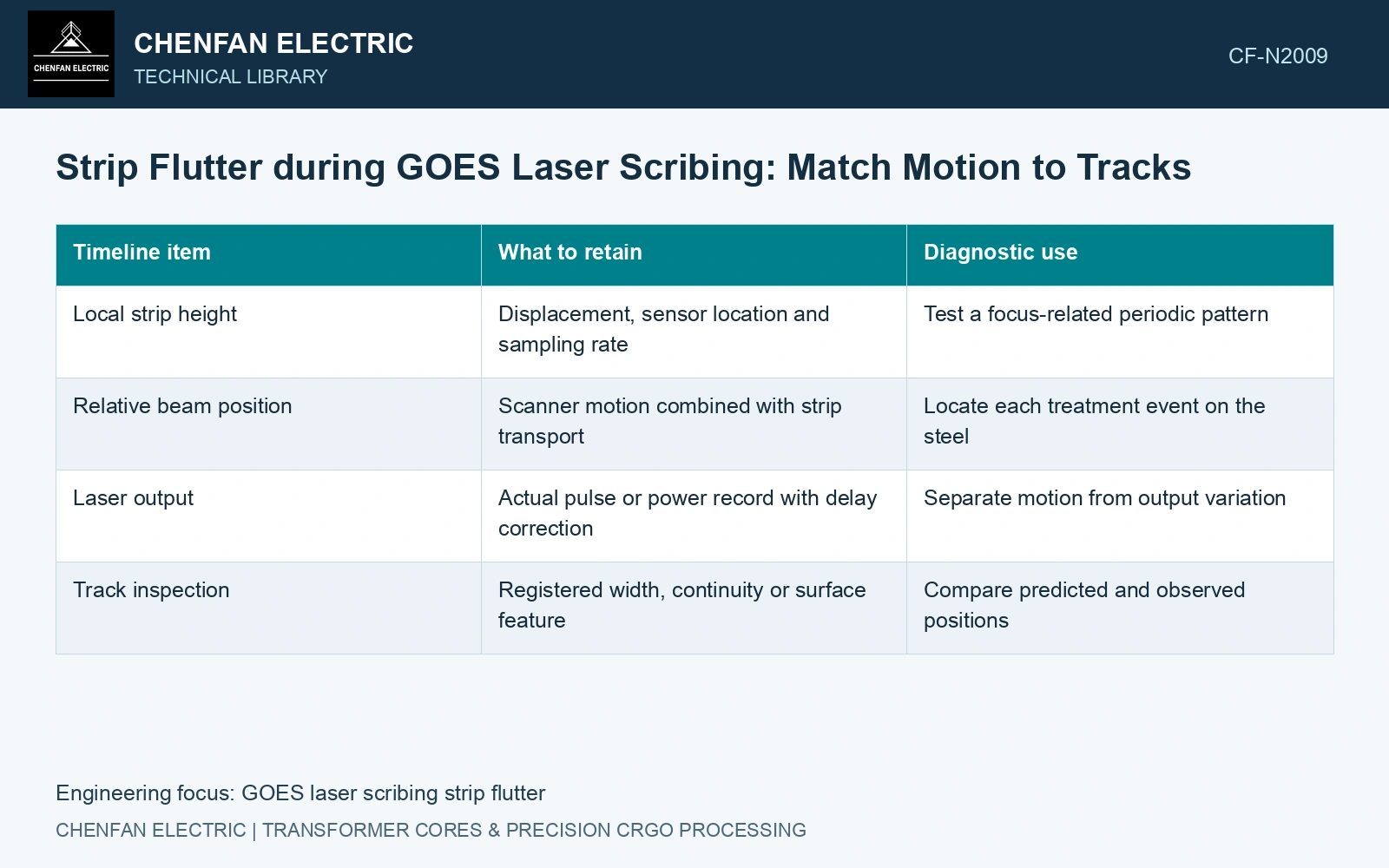
Use one time reference for the measured strip motion, actual beam-enable or pulse events, scanner position and material transport position. Convert the resulting track into material coordinates rather than retaining only machine coordinates.
| Timeline item | What to retain | Diagnostic use |
|---|---|---|
| Local strip height | Displacement, sensor location and sampling rate | Test a focus-related periodic pattern |
| Relative beam position | Scanner motion combined with strip transport | Locate each treatment event on the steel |
| Laser output | Actual pulse or power record with delay correction | Separate motion from output variation |
| Track inspection | Registered width, continuity or surface feature | Compare predicted and observed positions |
Convert measured velocity and vibration into material coordinates before comparing their spatial pattern. Integrate changing velocity through acceleration regions; a constant-speed conversion is valid only on its defined interval.
Test the connection before setting a tolerance
Look for stable phase and frequency relationships over several records. Check whether the pattern shifts as predicted when relative scan speed changes. Inspect the acquisition bandwidth and exposure time: an under-sampled camera can turn a fast movement into an apparently slow repeating defect.
The final response must include magnetic performance. Laser treatment changes domain structure and sheet loss under its specific test conditions [1]; a visible track difference is not a calibrated magnetic-loss measurement. Compare registered material at common B/f and preparation.
Catalogue gauge is 0.23 mm [2], not a focus tolerance. Assume normal flutter amplitude 0.10 mm, a qualified optical offset envelope ±0.08 mm and expanded height uncertainty ±0.01 mm. Even the nominal peak exceeds the envelope; its upper magnitude is 0.11 mm. Hold the process for support/focus correction. At assumed relative scan speed 2 m/s and vibration 100 Hz, the corresponding pattern period is 20 mm. Test phase and speed dependence on registered tracks before assigning causation or converting that displacement into a production magnetic tolerance.
Tension control, strip support, scan timing and focus tracking determine the treatment actually landing on the moving sheet. Record these signals on one time base and verify the resulting track geometry.
A useful flutter acceptance limit connects measured displacement to reproducible track and magnetic outcomes within a stated operating range. A displacement number copied from another machine has little meaning without its beam geometry, strip support and measurement bandwidth.
References
- P. Rauscher et al., The influence of laser scribing on magnetic domain formation in grain oriented electrical steel visualized by directional neutron dark-field imaging, Scientific Reports 6, 38307, 2016, Table 1. DOI: 10.1038/srep38307.
- Nippon Steel Corporation, Grain-Oriented Electrical Steel Sheets, catalogue D004je, April 2020, specification and typical-property tables.