

Register laser tracks against every step-lap cut datum before designing a paired core trial. A global phase shift may satisfy one layer while violating another; this note checks registration feasibility rather than predicting a joint-loss improvement.
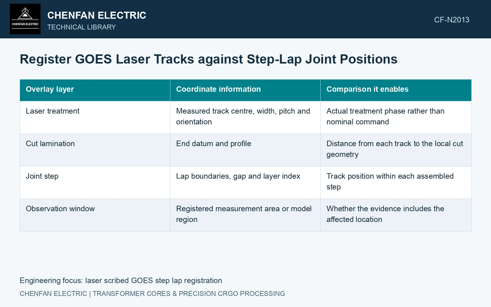
Put treatment and joint geometry on the same drawing
Define a material coordinate system with the rolling direction, a reproducible cut-end datum and the transverse direction. Plot the actual laser lines, cut profile, lap boundaries and intended gaps. For each step in the joint, retain the corresponding lamination number and orientation. A drawing of one exposed sheet cannot represent every layer in a stepped stack.
If regular tracks cross the rolling direction, describe their phase relative to the cut datum. For track pitch p and a selected track position x, the phase can be expressed as x modulo p, with its origin and sign convention stated. This is a registration descriptor; it is not a measure of joint performance.
| Overlay layer | Coordinate information | Comparison it enables |
|---|---|---|
| Laser treatment | Measured track centre, width, pitch and orientation | Actual treatment phase rather than nominal command |
| Cut lamination | End datum and profile | Distance from each track to the local cut geometry |
| Joint step | Lap boundaries, gap and layer index | Track position within each assembled step |
| Observation window | Registered measurement area or model region | Whether the evidence includes the affected location |
Change registration without changing the joint
A useful experiment changes the treatment phase while holding lap length, gap distribution, lamination grouping, material grade and clamping arrangement constant. Changing the cut length to achieve an offset can inadvertently alter the joint itself. If that cannot be avoided, the result describes a combined design change rather than an isolated registration effect.
Laser-scribing experiments show that treatment can change domain structure and magnetic response. They do not establish how any particular track phase interacts with a production step-lap joint. Local flux direction at the joint also differs from the nearly rolling-direction excitation used in many sheet tests. Keep that limitation visible when transferring sheet evidence. [1]
Use local observations and whole-core results together
Inspect the registered joint region for a repeatable change in magnetic or thermal behaviour under the selected excitation. Interpret any local model only within its material law, mesh and treatment representation. An attractive calculated field plot is not experimental confirmation that a track offset improves the core.
Use catalogue gauge 0.23 mm [2] in an assumed five-step, one-sheet-per-step joint: nominal steel sequence thickness is 1.15 mm. Assume cut datums differ by 1 mm between successive steps and laser pitch is 5 mm. Their phases cover residues 0, 1, 2, 3 and 4 mm. A common phase shift of 0.5 mm gives nearest-track distances 0.5, 1.5, 2.5, 1.5 and 0.5 mm: minimum 0.5 mm. That is the best possible minimum for this 1 mm residue grid. If a fictional process rule requires each track at least 0.6 mm from every cut datum, no global phase works. Revise pitch, step registration or the justified exclusion rule before comparing magnetic performance; equal steel area does not resolve that geometric conflict.
Track origin, cut datum, lap offset and packet sequence determine the installed registration. Carry those coordinates from strip treatment through cutting and stacking, including the uncertainty of each datum transfer.
Evaluate no-load loss and excitation on otherwise matched assemblies. Report the measured phase distribution, including positioning scatter, with those results. The useful outcome is a tested registration range for a defined joint construction, or evidence that its influence is too small to distinguish under those conditions.
References
- P. Rauscher et al., The influence of laser scribing on magnetic domain formation in grain oriented electrical steel visualized by directional neutron dark-field imaging, Scientific Reports 6, 38307, 2016, Table 1. DOI: 10.1038/srep38307.
- Nippon Steel Corporation, Grain-Oriented Electrical Steel Sheets, catalogue D004je, April 2020, specification and typical-property tables.