

In a forced-gas design, total blower flow can divide between useful winding paths and bypasses. DOE’s fluid-flow treatment connects branch flow to the shared pressure network [1]. Wu et al. analyse a particular gas-transformer thermal field [2], not the flow split of this winding.
Trace the route from inlet to winding passages, outlet and external cooler. Include flow-guiding parts and insulating barriers in the same geometry.
Match heat pickup to the path
For a steady stream with known properties, bulk pickup is Q = ṁcp(Tout−Tin) [3], in W, kg/s, J/(kg·K) and K. Include density when converting volumetric flow. This balance does not establish the hottest conductor temperature.
Volumetric flow alone does not supply ṁ without density. The actual gas state therefore belongs in the cooling record. Bulk pickup also does not directly establish the hottest conductor temperature.
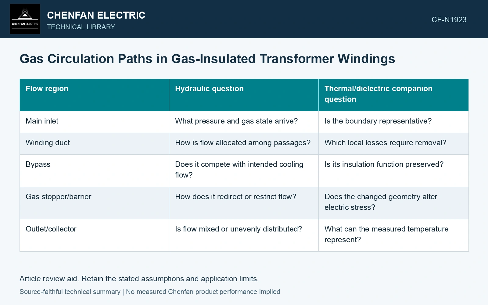
| Flow region | Hydraulic question | Thermal/dielectric companion question |
|---|---|---|
| Main inlet | What pressure and gas state arrive? | Is the boundary representative? |
| Winding duct | How is flow allocated among passages? | Which local losses require removal? |
| Bypass | Does it compete with intended cooling flow? | Is its insulation function preserved? |
| Gas stopper/barrier | How does it redirect or restrict flow? | Does the changed geometry alter electric stress? |
| Outlet/collector | Is flow mixed or unevenly distributed? | What can the measured temperature represent? |
Assess the parallel routes
Flow follows the pressure balance of the connected paths. Increasing total blower capacity does not automatically correct a poorly distributed network. A design change can increase one path’s flow while leaving another’s local transfer nearly unchanged.
Look for local dead regions
A stagnant or weak-flow region can receive heat through adjacent solid insulation even when bulk outlet gas appears acceptable. The model should retain local loss and heat paths. Sensor location and mixing determine whether a measurement can reveal that region.
Manufacturing or repair can change duct geometry. A displaced spacer or revised barrier is both a hydraulic and dielectric change; document its effect on both questions.
Verify the assembled flow case
The qualification should name gas composition/state, blower configuration and winding geometry. Compare the chosen flow model with suitable evidence and retain uncertainty in inaccessible regions.
Assume total flow 0.20 kg/s initially splits 0.10/0.10 between winding/bypass. A fictional stopper change gives 0.16/0.04 at unchanged total flow, increasing useful flow 60%. With assumed cp = 700 J/(kg·K) and allowed bulk rise 40 K, useful heat transport rises 2.80→4.48 kW [3]. It crosses an assumed 4 kW winding duty, but only within this prescribed split. Validate actual branch losses, local heat transfer and dielectric geometry before crediting the stopper; the unchanged total reading cannot demonstrate that improvement.
When total circulation appears adequate but a conductor remains hot, the question is how much mass flow reaches that duct and whether its heat can reach the gas. Increasing blower capacity can favour a bypass rather than the controlling passage. A duct or stopper change must therefore be checked for local cooling and electric-field consequences together.
References
- U.S. Department of Energy, DOE-HDBK-1012/3-92, Thermodynamics, Heat Transfer, and Fluid Flow, Volume 3, 1992.
- Y. Wu et al., Research on Heat Dissipation Performance of Eco-friendly Gas insulated Transformer with i-C4F7N/CO2 as the Insulation Medium, Journal of Physics: Conference Series 2527, 012011, 2023. DOI: 10.1088/1742-6596/2527/1/012011.
- U.S. Department of Energy, DOE-HDBK-1012/2-92, Thermodynamics, Heat Transfer, and Fluid Flow, Volume 2, 1992.