

A gas-transformer heat run records behaviour in its tested cooling state. Wu et al. analyse a particular natural-gas/natural-air cooled gas transformer [1]. An underground installation needs its own exchanger-inlet, internal-flow and cooling-outage comparison.
Capture the gas-side condition
Record gas identity, composition where relevant, density or verified inventory basis, pressure reference and temperature measurements. The gas-side flow measurement or validated flow estimate should identify where it was obtained and which winding paths it represents. A blower running at rated speed does not prove that a partly obstructed winding duct receives its intended flow.
Retain the installed baffles, barriers and gas stoppers. A temporary factory configuration with a different flow route can change the relationship between average gas temperature and winding hot spots. The thermal comparison must use the final internal geometry or justify the difference.
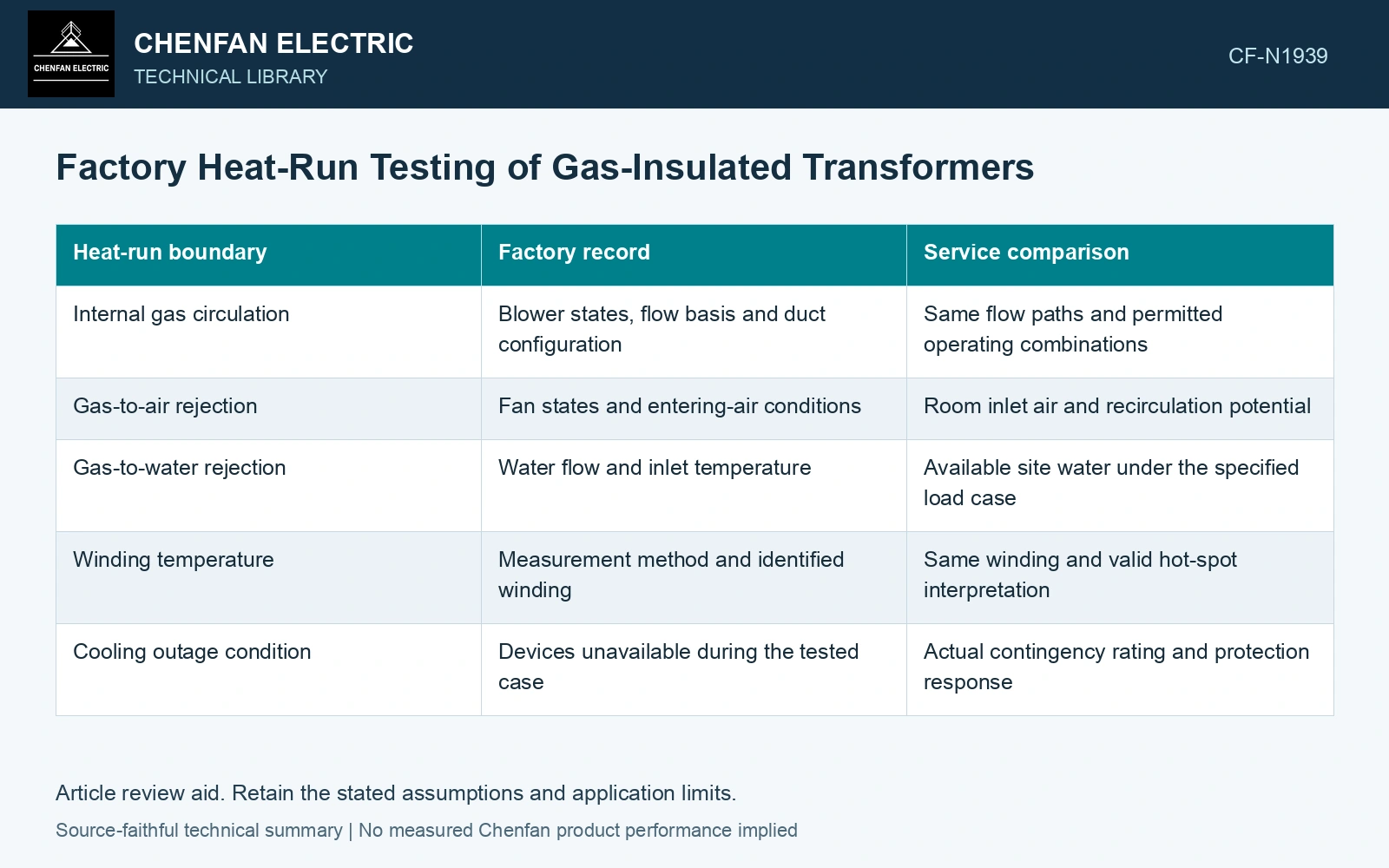
| Heat-run boundary | Factory record | Service comparison |
|---|---|---|
| Internal gas circulation | Blower states, flow basis and duct configuration | Same flow paths and permitted operating combinations |
| Gas-to-air rejection | Fan states and entering-air conditions | Room inlet air and recirculation potential |
| Gas-to-water rejection | Water flow and inlet temperature | Available site water under the specified load case |
| Winding temperature | Measurement method and identified winding | Same winding and valid hot-spot interpretation |
| Cooling outage condition | Devices unavailable during the tested case | Actual contingency rating and protection response |
Compare heat rejection at its inlet
For an air-cooled exchanger, outdoor ambient temperature may differ from the air actually entering the exchanger. Room recirculation can raise inlet temperature even when the outside weather meets the design basis. For a water-cooled exchanger, the relevant inlet is the supplied water, with its temperature and flow conditions.
If water subsequently rejects heat to air in a separate system, that second stage can constrain continuous operation. Include it in the site thermal assessment even when it is outside the transformer’s factory test boundary.
Keep extrapolation tied to a validated method
A correction method developed for an oil-filled transformer should not be assumed valid for gas circulation. Gas properties, forced-flow behaviour and internal heat-transfer relationships are different. Ask which measured quantities and model support any correction to another ambient or cooling state.
For a fictional heat-run balance, assume input loss 20 kW, gas mass flow 0.50 kg/s and cp = 700 J/(kg·K) at the evaluated state. The bulk rise to carry all heat is 57.14 K from Q = ṁcpΔT [2]. An independently assumed 40 K reading accounts for 14 kW, leaving 6 kW to tank rejection, other cooling paths or measurement mismatch. Close that balance before fitting a winding coefficient; the example is not a measured result.
Separate an observed heat-run result from a calculated service prediction in the report. If the site changes exchanger inlet conditions or permits operation with fewer cooling devices, the prediction needs explicit supporting evidence. This comparison reveals whether the tested rating reaches the installed thermal boundary, or whether an apparently complete factory result leaves a site-side cooling limit unresolved.
References
- Y. Wu et al., Research on Heat Dissipation Performance of Eco-friendly Gas insulated Transformer with i-C4F7N/CO2 as the Insulation Medium, Journal of Physics: Conference Series 2527, 012011, 2023. DOI: 10.1088/1742-6596/2527/1/012011.
- U.S. Department of Energy, DOE-HDBK-1012/2-92, Thermodynamics, Heat Transfer, and Fluid Flow, Volume 2, 1992.