

A smoothing reactor carries a direct-current component together with time-varying ripple. The direct component establishes magnetic bias; the ripple produces a cyclic excursion around that operating region. Selecting a core from an alternating-current transformer loss value alone misses both the biased inductance requirement and the waveform that produces the losses.
Describe the current with more than one number
Write the current conceptually as i(t) = IDC + iripple(t). State the average direct current, the maximum instantaneous current, the ripple waveform or spectrum, and the duration of the relevant duty. Root-mean-square current is useful for some thermal calculations but does not preserve the peak or spectral information.
Inductor design guidance distinguishes operating modes and the relationship between current excursion, flux excursion and stored energy. [1] Its switching-converter examples illustrate the principles, not universal limits for large smoothing reactors.
A ripple percentage without its definition is ambiguous. Identify whether it means peak-to-peak ripple divided by average current, ripple root-mean-square value, or another project-defined measure.
Use the inductance that answers the circuit question
For a single-valued, locally linearized relation around a biased operating point, differential inductance is the local slope of flux linkage against current; software may call this incremental inductance. [3] A finite-ripple or measured AC value also needs its amplitude, frequency and extraction method. With hysteresis, it must reflect the relevant minor-loop response rather than automatically use the slope of a normal magnetization curve. A secant value from the origin is a different quantity. [2]
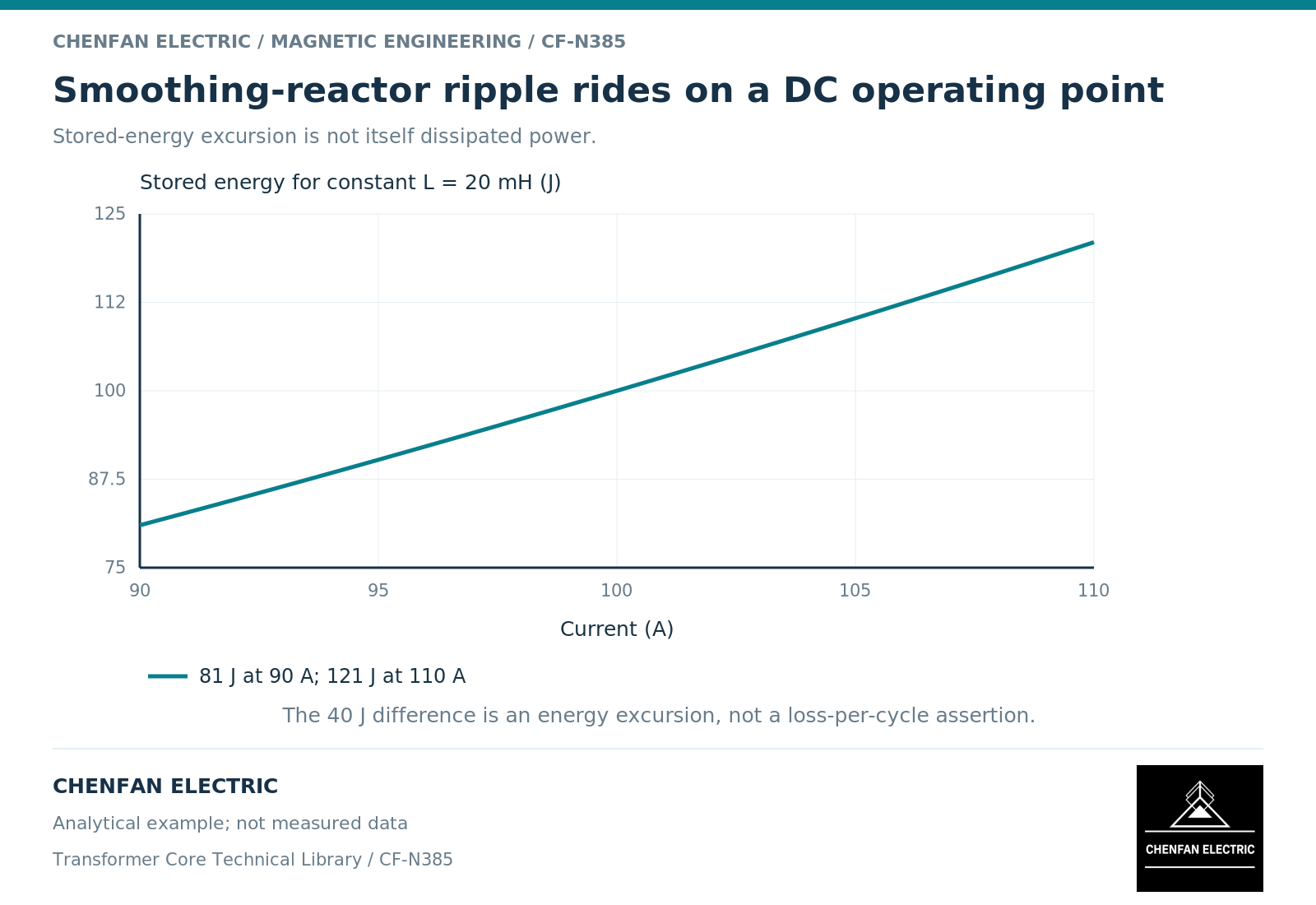
As an illustrative linear example, a 0.020 H reactor with a 100 A direct current and a ±10 A triangular ripple reaches 110 A peak. Its ideal stored energy ranges from 81 J at 90 A to 121 J at 110 A. This does not imply a 40 J loss per ripple cycle: energy can be returned to the circuit.
If inductance changes significantly across that range, the linear example no longer describes the actual energy or ripple response. Use the appropriate nonlinear relationship and clearly identify the measurement or model basis.
Separate bias, ripple loss and winding heating
A constant direct component does not by itself create repeated alternating hysteresis cycles in steady state. It can nevertheless shift the operating region and change the response to ripple. The winding also dissipates resistive heat from its current, with additional frequency-dependent effects where relevant.
| Requirement | Necessary definition |
|---|---|
| Bias capability | Current range and magnetic operating point |
| Ripple attenuation | Incremental or large-signal inductance over the duty |
| Core loss | Actual cyclic flux trajectory and material condition |
| Winding loss | Direct and alternating current components |
| Local gap heating | Fringing exposure and conductor arrangement |
| Transient duty | Current excursion, duration and recovery condition |
A small-signal inductance measured without bias does not establish all these quantities. Nor does a sinusoidal material test reproduce an arbitrary biased minor loop.
Release a waveform-based requirement
Provide the intended current and voltage waveforms, frequency content, operating range and required inductance definition. Where those inputs are still uncertain, retain them as an explicit design range rather than inventing a representative waveform that looks convenient.
The core choice must then be reviewed with gap geometry, winding arrangement, cooling and mechanical support. A material substitution can change more than loss; it can alter the usable bias range and assembly constraints.
This comparison is educational, not a declaration that Chenfan Electric supplies a qualified smoothing-reactor product. For any such project, the responsible reactor designer must establish the magnetic and assembly requirements and the evidence needed to verify them.
References
[1] Lloyd Dixon / Texas Instruments. Magnetics Design 5 – Inductor and Flyback Transformer Design.
[2] Cesare Tozzo / COMSOL. Modeling Ferromagnetic Materials in COMSOL Multiphysics.
[3] QuickField / Tera Analysis. Apparent and incremental magnetic permeability.