

A spacer’s maximum free thickness may not equal the cooling duct’s assembled opening. The stack contacts particular regions of the spacer, and those regions may compress or seat differently from an exposed end measured with a caliper.
Define the surfaces that carry the load and the condition in which their separation matters. If the drawing controls an assembled duct, the inspection should connect the spacer measurement to that assembly state. A convenient dimension on an unloaded projecting end may have little relation to it.
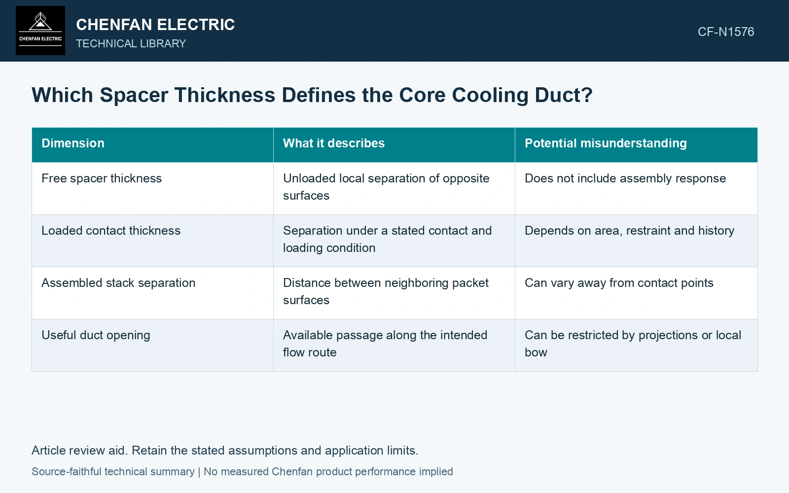
Name each dimension separately
| Dimension | What it describes | Potential misunderstanding |
|---|---|---|
| Free spacer thickness | Unloaded local separation of opposite surfaces | Does not include assembly response |
| Loaded contact thickness | Separation under a stated contact and loading condition | Depends on area, restraint and history |
| Assembled stack separation | Distance between neighboring packet surfaces | Can vary away from contact points |
| Useful duct opening | Available passage along the intended flow route | Can be restricted by projections or local bow |
The highest contact regions may set the initial spacing while leaving other regions out of contact. Conversely, local compression can reduce their prominence. Record where the measurement is taken rather than giving one unlabeled thickness for a nonuniform part.
Reproduce the contact condition
Use contact faces and loading conditions representative of the intended function, within an approved test procedure. The same force applied through different contact areas does not produce the same nominal pressure. Surface flatness and alignment also affect which region carries load.
Measure relevant positions before loading, under the defined condition and after unloading if permanent seating matters. A change after the first cycle should not be hidden by reporting only the stabilized value. It may reflect an assembly process that requires explicit control.
This comparison establishes geometry under those conditions. It does not by itself qualify creep, material strength or compatibility with an insulating liquid.
Follow the actual passage
An end projection can obstruct a duct even when it does not determine packet separation. Measure its location and extent separately. Likewise, a clear entrance does not prove that the passage remains open farther inside.
For a simplified straight rectangular passage, local geometric area is width multiplied by opening height. Use that relation only where the assumed shape exists. A duct containing spacer footprints, local closures or changing packet surfaces needs a mapped usable cross-section rather than a nominal width-times-thickness calculation.
Compare the assembled geometry with the approved cooling layout. Where direct inspection is impossible, qualify the indirect dimensional method against accessible representative assemblies. Do not infer internal clearance solely from a spacer protruding outside the stack.
When a duct is undersized, locate the cause: spacer thickness, contact seating, packet bow or an obstruction. Increasing every spacer’s nominal thickness may conceal one problem while changing core build and other clearances. A functionally defined measurement directs the correction to the surface or region that actually controls the passage.
Calculate the useful duct after seating and obstruction
23ZH90 nominal sheet thickness is 0.23 mm [1]. Assume packets of 100 sheets on each side of a duct, a 4.00 mm free spacer that seats to 3.70 mm, a 100 mm passage width, and a 10 mm wide spacer footprint. Steel-only packet thickness is 23.0 mm on each side. The useful rectangular flow area is (100 − 10) × 3.70 = 333 mm²; using free thickness would give 360 mm², overstating area by 8.1%. With an assumed minimum useful area of 340 mm², this geometry fails that requirement. Verify seated thickness and internal blockage before changing the build; report measurement uncertainty on the limiting dimensions [2].
Manufacturing controls. Spacer thickness distribution, seating load, packet bow, local burrs and end projections control the useful opening. Duct geometry and thermal performance require separate verification; a nominal steel sum excludes both coatings and interface gaps.
References
- Nippon Steel Corporation, Grain-Oriented Electrical Steel Sheets, catalogue D004je_03_202004, 2020, Specifications; Size and Form Tolerances.
- JCGM, JCGM 100:2008, Evaluation of measurement data — Guide to the expression of uncertainty in measurement, 2008.