

Measuring each T-joint edge against its own convenient reference can produce two passing angles and a joint that does not close. The joint depends on their relationship to the same limb centerline and mating geometry, including position as well as angle.
Establish the functional reference system first. Fit the specified limb centerline or center plane, then locate both edge profiles within it. Record the measurement regions so that a rounded corner or burr does not change the fitted line without being noticed.
Predict the separation across the contact region
For a local comparison, let g₀ be the edge separation at a defined reference point, and let δ₁ and δ₂ be the small rotations of the two mating edges in a common signed coordinate system. At distance x from the reference point, the approximate separation is g(x) = g₀ + x(δ₁ − δ₂), with x and g in millimetres and angles in radians.
The signs must follow the actual geometry. An inspector cannot simply add two unsigned angle deviations and call the result a gap. Where small-angle assumptions are unsuitable, calculate the intersection and separation directly from the fitted lines.
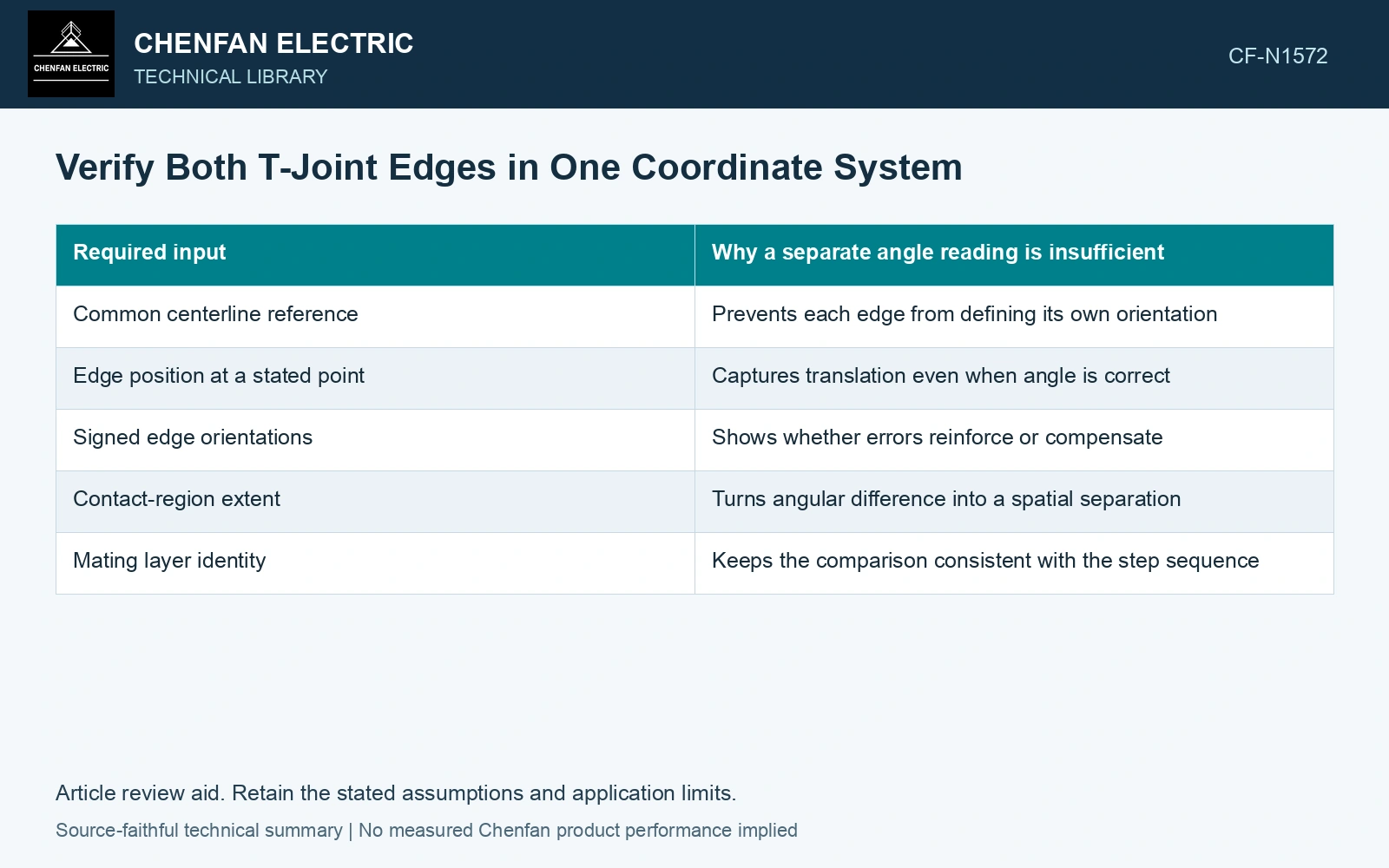
| Required input | Why a separate angle reading is insufficient |
|---|---|
| Common centerline reference | Prevents each edge from defining its own orientation |
| Edge position at a stated point | Captures translation even when angle is correct |
| Signed edge orientations | Shows whether errors reinforce or compensate |
| Contact-region extent | Turns angular difference into a spatial separation |
| Mating layer identity | Keeps the comparison consistent with the step sequence |
Plot or tabulate g(x) across the intended contact region. Check for both excessive opening and geometric overlap. A negative calculated separation may indicate an interference in the idealized rigid profile; actual assembly then depends on sheet movement or deformation.
Compensation can conceal a wrong profile
If two angle errors compensate in one position, the joint may appear closed while the limb is displaced from its intended axis. Conversely, correct angles can still leave a uniform gap when the cut edges are translated apart.
Use assembled closure as a cross-check, not as a substitute for individual profile conformity. The drawing may control both because later layers, winding alignment and interchangeability depend on them.
Repeat the prediction for the relevant layer patterns rather than applying one outer-surface measurement to a buried step sequence. Inspection before closure can preserve the needed profile evidence. After assembly, visible edges may not reveal the internal mismatch.
When the calculated and observed closure disagree, inspect the datum transfer and sheet seating. Compare the same layer and the same measurement plane. A T-joint assessment becomes useful when it explains where the two profiles meet, rather than ending with two unrelated angle values that happen to be inside tolerance.
Compare signed edge errors across a real stock width
Take 300 mm nominal width in the catalogue 150–400 mm band for 0.23 mm stock [1]. For a geometric demonstration, assume the same 300 mm contact span, initial gap g₀ = 0.10 mm, signed edge rotations δ₁ = +0.03° and δ₂ = −0.02°, and a 0.30 mm maximum opening. Then g(300) = 0.10 + 300 tan(0.05°) = 0.362 mm. If both rotations were positive, the difference would instead be 0.01° and the end gap 0.152 mm. Opposite signs change the disposition. Verify common-axis registration and uncertainty before accepting either result [2]; the stock width tolerance itself sets no joint-gap limit.
Manufacturing controls. Cut angle, cutter position, cut length and packet registration determine joint closure. Inspect both mating edges in the same coordinate system and retain their layer positions; correcting one unsigned angle alone can increase the assembled gap.
References
- Nippon Steel Corporation, Grain-Oriented Electrical Steel Sheets, catalogue D004je_03_202004, 2020, Specifications; Size and Form Tolerances.
- JCGM, JCGM 100:2008, Evaluation of measurement data — Guide to the expression of uncertainty in measurement, 2008.