

Oil and pressboard do not necessarily share DC voltage in the same proportions immediately after energization and after a long hold. Permittivity governs an ideal fast capacitive response; conductivity governs the ideal stationary conduction response. Confusing these regimes can hide the most highly stressed layer. Apply the HVDC transformer specification framework of IEC/IEEE 60076-57-129 to the stated liquid-immersed equipment [1]. [2]
Consider two flat layers in series, with thicknesses do and dp, uniform area and no edge effects. Under ideal steady conduction, equal current density gives σoEo = σpEp. Thus Eo/Ep = σp/σo, and V = Eodo + Epdp.
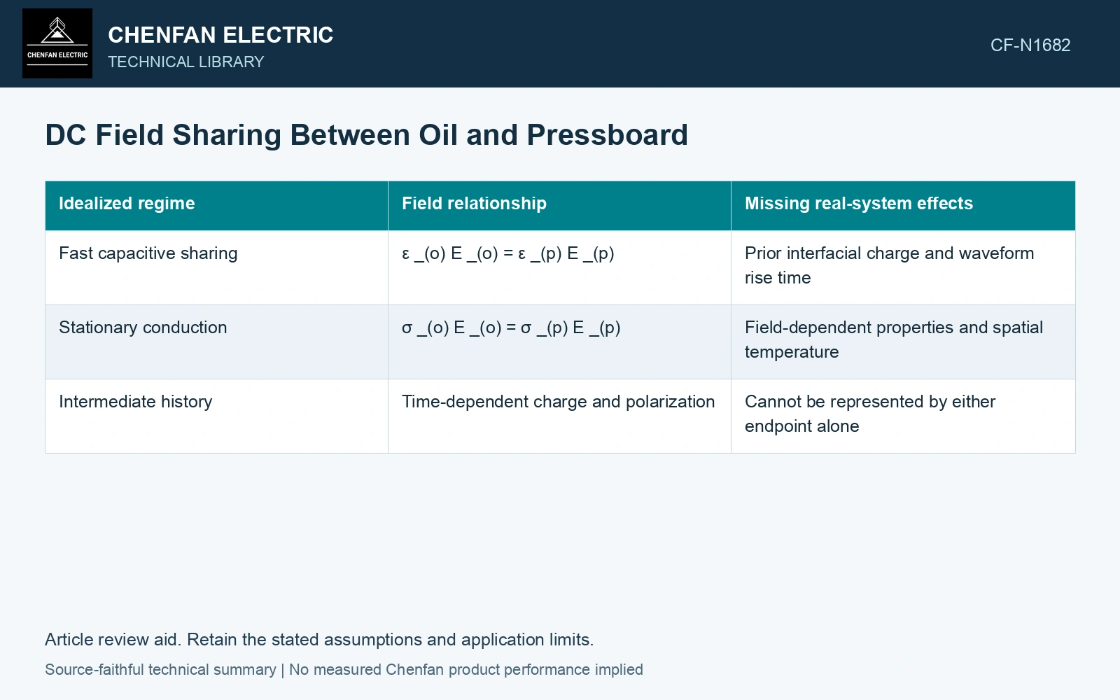
Use the ratio as a sensitivity, not a constant
| Idealized regime | Field relationship | Missing real-system effects |
|---|---|---|
| Fast capacitive sharing | εoEo = εpEp | Prior interfacial charge and waveform rise time |
| Stationary conduction | σoEo = σpEp | Field-dependent properties and spatial temperature |
| Intermediate history | Time-dependent charge and polarization | Cannot be represented by either endpoint alone |
Here ε is absolute permittivity in F/m, σ conductivity in S/m, E field in V/m, d thickness in metres and V applied volts. These expressions assume linear homogeneous layers. They do not include local space-charge injection or an actual converter-transformer barrier edge.
Calculate both endpoint field partitions
Assume 100 kV across 5 mm of oil and 10 mm of pressboard at fixed temperature. With σoil = 10⁻¹² S/m and σboard = 10⁻¹³ S/m, stationary fields are Eoil = 100/(5 + 10 × 10) = 0.952 kV/mm and Eboard = 9.524 kV/mm. With assumed relative permittivities 2.2 and 4.4, initially uncharged capacitive sharing instead gives 10.0 and 5.0 kV/mm. The oil field changes by a factor of 10.5 between these ideal endpoints. Evaluate both endpoints and the transition; neither average applied field nor one property ratio is an acceptance criterion.
Vary both material properties
For the stationary model, Eo = V/[do + dp(σo/σp)]. Increasing oil conductivity relative to pressboard moves more voltage into the pressboard in this ideal series path. The effect depends on the thickness ratio; a conductivity ratio alone does not specify the absolute field.
Use measured property ranges at relevant temperature and field, then recalculate. If conductivity depends strongly on field, solve the current-continuity relation consistently rather than inserting a value measured at a different stress. A temperature gradient can make the local property ratio differ from a bulk laboratory value.
The calculation provides a check on direction and parameter sensitivity. It cannot establish a safe operating field. Design qualification requires the actual barrier geometry, interfaces, voltage history and material evidence, including conditions where the simple two-layer assumptions cease to describe the system.
References
- IEC/IEEE, IEC/IEEE 60076-57-129:2017, Power transformers – Part 57-129: Transformers for HVDC applications.
- CIGRE JWG A2/B4.28, Technical Brochure 406, HVDC Converter Transformers – Design review, test procedures, ageing evaluation and reliability in service, 2010.