

A spare GSU with the right MVA rating may still be unsuitable for a second generator. Different terminal voltages change current, bus connection and the ratio needed to reach the grid voltage. Compatibility must be checked for each unit and each required operating point. Set the general power-transformer specification under IEC 60076-1 [1].
At balanced three-phase operation, I = S/(√3 V). For the same apparent power, the lower generator voltage requires more LV current. A tap range that reaches the nominal voltage ratio does not increase the winding or terminal current capability automatically.
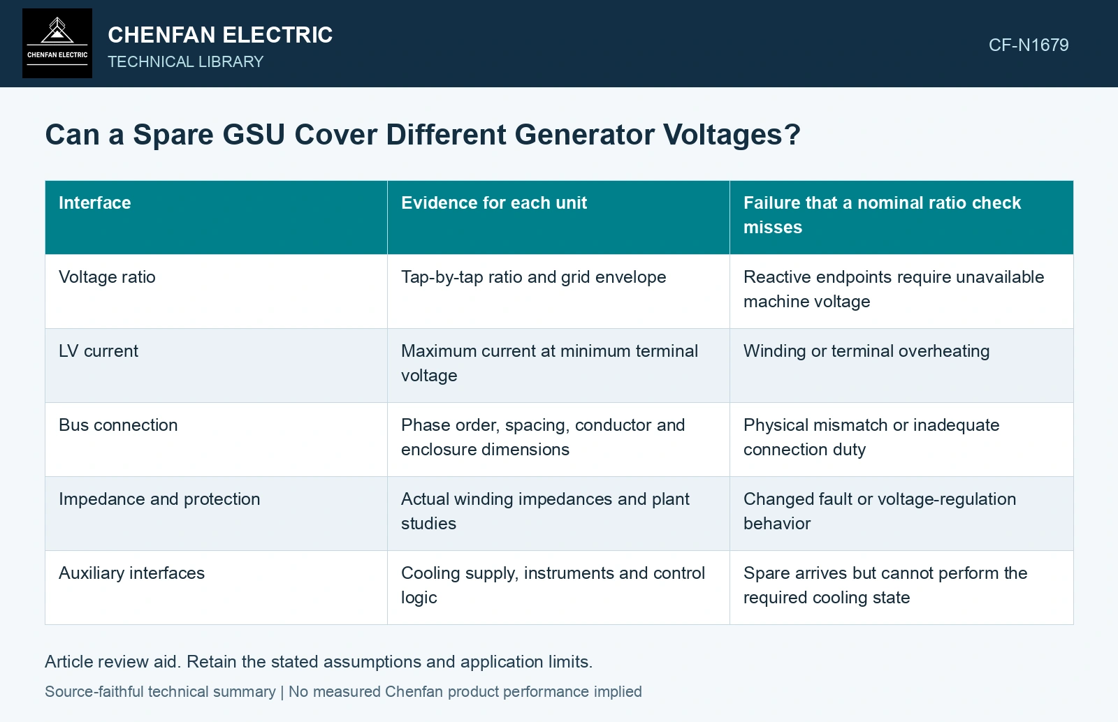
Make the compatibility matrix unit-specific
| Interface | Evidence for each unit | Failure that a nominal ratio check misses |
|---|---|---|
| Voltage ratio | Tap-by-tap ratio and grid envelope | Reactive endpoints require unavailable machine voltage |
| LV current | Maximum current at minimum terminal voltage | Winding or terminal overheating |
| Bus connection | Phase order, spacing, conductor and enclosure dimensions | Physical mismatch or inadequate connection duty |
| Impedance and protection | Actual winding impedances and plant studies | Changed fault or voltage-regulation behavior |
| Auxiliary interfaces | Cooling supply, instruments and control logic | Spare arrives but cannot perform the required cooling state |
Keep physical and electrical drawings tied to the same transformer configuration. Removable connection adapters may solve geometry but introduce new joints, conductor forces or insulation clearances. Their duty requires its own assessment.
Do not stop at the rated point
Plot each generator’s P–Q envelope with the spare’s current limits at the relevant voltage. Check both reactive supply and absorption, startup reverse feed and any condenser operation. The spare may cover a restricted envelope even when it cannot replace the original unit at every point.
Compare phase displacement and terminal markings before planning connections. An incorrect phase relationship is not a problem to resolve during energization. Protection ratios and settings, cooling interlocks and monitored temperature channels also need the spare configuration identified.
Rate the spare current at the lower generator voltage
Assume balanced 50 Hz service at 100 MVA. At 15.75 kV line-to-line, LV current is 100 × 10⁶/(√3 × 15,750) = 3666 A; at 13.8 kV it is 4184 A, 14.13% higher. An assumed spare LV limit of 4000 A permits only √3 × 13.8 × 4 = 95.61 MVA at the lower voltage. Restrict that operating envelope or select another spare even if taps cover both nominal ratios. Connection, insulation and protection checks remain independent.
State any restricted service clearly
If the spare is acceptable only at limited current, specified taps or a smaller reactive range, turn those conditions into an operating schedule supported by the studies. Distinguish a calculated restriction from a permanent transformer nameplate rating.
A fleet spare decision is strongest when the matrix shows why every required interface fits, or exactly which one restricts service. “Same MVA and similar voltage” is a screening description, not an interchangeability conclusion.
For mineral-oil equipment, relate the loading assessment to operating temperature and thermal ageing [2].
References
- IEC, IEC 60076-1:2011, Power transformers – Part 1: General.
- IEC, IEC 60076-7:2018, Power transformers – Part 7: Loading guide for mineral-oil-immersed power transformers.