

Converter-related direct-current injection must be qualified at the actual transformer interface. The presence of a converter does not establish the magnitude, path or duration of a bias current in the transformer. Start with the converter and network behavior, then evaluate the resulting magnetic and thermal duty.
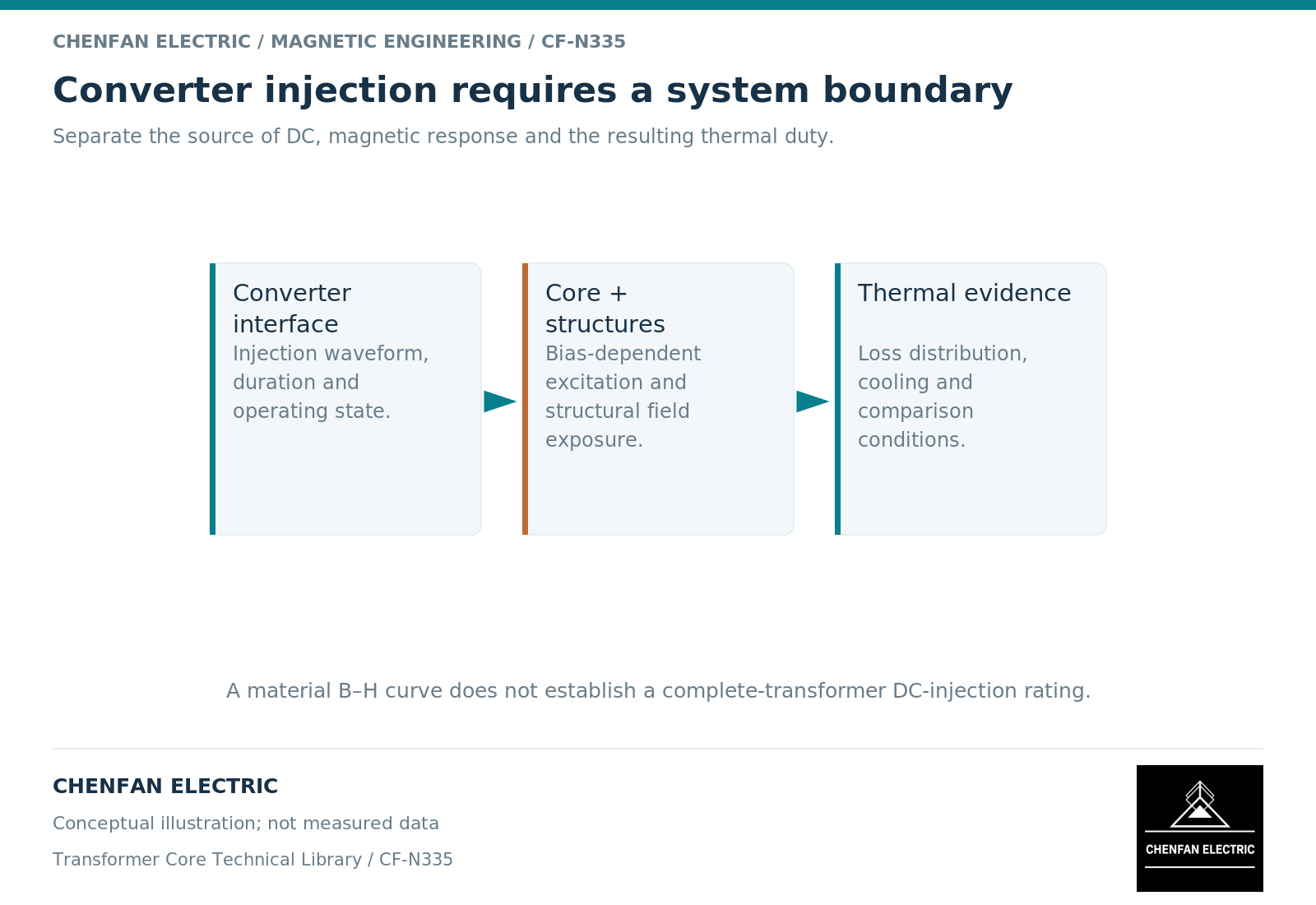
Define what reaches the winding
A converter-side current description may refer to a semiconductor leg, a filter branch, a line conductor or a transformer winding. Those are different boundaries. Filters, connections and control behavior can change the component that reaches the transformer.
Request a time-domain current and voltage definition at the named transformer terminals, including the reference direction and operating mode. A percentage labeled “DC injection” is incomplete without its reference current, averaging interval and measurement location.
The distinction between transient offset and sustained bias also matters. An event during startup or a fault response should not be treated as a continuous operating condition unless the specification actually requires that duty.
Couple bias with the alternating excitation
A bias current creates ampere-turns while the alternating induced voltage determines flux change. The core response must satisfy both within the winding circuit. Nonlinear magnetic modeling distinguishes a simple B-H relation from a history-dependent trajectory. [1]
The assessment should include turns, tap position, winding connection, core topology and the relevant source impedance. A generic core curve does not determine the current distribution through the complete converter-transformer system.
An illustrative specification error is to state only a permitted direct-current percentage while omitting the alternating voltage and frequency. The same bias can interact differently with a core already operating at a higher volts-per-turn condition. The combined envelope is the engineering requirement.
Follow additional loss to its location
Heating may arise in windings, core regions or nearby conducting structures. A total current increase is not a complete loss allocation. Harmonic components and local fields can affect where energy is dissipated.
A field model distinguishes magnetic material response from conducting eddy-current regions. [2] The thermal model then needs those heat sources, their duration and the cooling boundary. A no-load material loss value cannot be stretched into a prediction of all converter-related heating.
| Qualification input | Required clarification |
|---|---|
| Injection quantity | Terminal, units, polarity and averaging method |
| Operating mode | Normal, startup, transient or fault-related duty |
| Alternating excitation | Voltage waveform, frequency and tap |
| Loading | Winding currents and harmonic content |
| Duration | Continuous, intermittent or event time history |
| Acceptance evidence | Measurement, validated calculation or justified comparison |
Keep capability statements within the evaluated envelope
A statement that a transformer is suitable for one converter project should identify the actual design and duty. It does not imply suitability for every converter topology or control mode.
Likewise, an educational discussion of bias is not evidence that a core supplier manufactures or certifies a complete converter transformer. Chenfan Electric’s core-related scope should be stated through the supplied core geometry, material and agreed verification records.
The practical handover is a jointly defined excitation envelope and a traceable assessment of its consequences. Where the converter data are incomplete, mark the unresolved input rather than inserting a universal allowable bias current. That keeps the quotation and technical approval aligned with the real system instead of an undefined percentage.
References
[1] Cesare Tozzo / COMSOL. Modeling Ferromagnetic Materials in COMSOL Multiphysics.
[2] David Meeker. Finite Element Method Magnetics User Manual.