

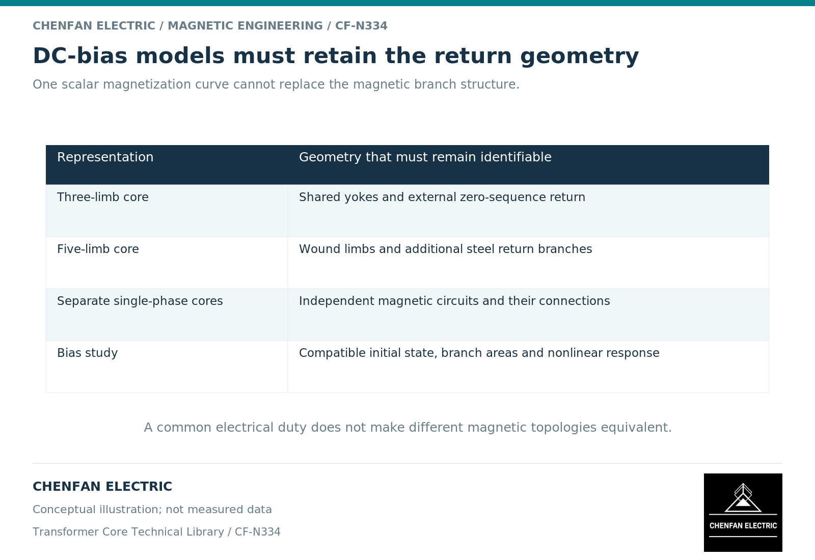
Core geometry cannot be omitted from a direct-current-bias study when magnetic return paths affect the result. Limb count, shared yokes, outer return sections and surrounding structures determine how the biased excitation is distributed. A material curve supplies constitutive behavior, not the complete magnetic circuit.
Bias acts through a connected magnetic network
The winding ampere-turns drive a network of reluctances. In a shared three-phase core, one branch’s response can affect others through common yokes and return paths. Five-limb and three-limb constructions do not provide the same routes for every flux component.
Geometrical transformer models explicitly distinguish these coupled paths. [1] That is the relevant reason to preserve topology in the study; it is not a reason to rank all designs by limb count alone.
An outer return limb may have a different area from a wound limb. Its flux-density duty must be calculated from its own combined branch flux and net section. A single average density assigned to the entire core can conceal the controlling region.
Avoid declaring any topology immune
An additional iron return can change reluctance and flux distribution, but it does not remove nonlinearity, winding losses or structural coupling. A design with one favorable response metric may be less favorable in another case.
Likewise, a higher external reluctance does not automatically establish a harmless response. The complete winding circuit determines the ampere-turn balance, and fields outside the main core can interact with conducting structures.
The meaningful comparison holds the electrical duty constant while changing a defined geometric feature. If voltage, turns, winding connection and enclosure also change, the result belongs to the complete design comparison rather than to one topology label.
Match geometric detail to the required observable
For terminal current or reactive demand, a validated magnetic equivalent circuit may provide sufficient detail. For local clamp or tank loss, a distributed field model can be necessary. The chosen constitutive model must also represent the nonlinear or history-dependent behavior used by the study. [2]
Do not confuse a detailed drawing with a validated model. Joint representation, material axes, external domain and winding sources can still be wrong in a visually accurate three-dimensional assembly.
A useful sensitivity study varies the uncertain return-path and material parameters while preserving physically possible geometry. If the conclusion changes substantially, the missing evidence should be prioritized before a capability claim is made.
Create a geometry-to-result trace
| Geometric input | Result that may depend on it |
|---|---|
| Limb and yoke net areas | Branch flux density and nonlinear onset |
| Shared-path lengths | Magnetic coupling and excitation demand |
| Outer return arrangement | Distribution of common-mode components |
| Winding placement | Leakage field and structural coupling |
| Tank and clamp geometry | Local induced losses and thermal concentration |
The trace should reference the exact drawing revision used in the model. A later change to a return section or structural spacing requires review even when the principal wound-limb diameter remains unchanged.
For a core supplier, this produces a precise manufacturing boundary: the controlled geometry and material definition that the transformer designer evaluated. It avoids an unsupported request to certify “DC-bias capability” from steel grade alone. The final qualification belongs to the complete electrical, magnetic and thermal configuration, with the evaluated duty and remaining uncertainties stated.
References
[1] Manitoba Hydro International / PSCAD. The UMEC Approach.
[2] Cesare Tozzo / COMSOL. Modeling Ferromagnetic Materials in COMSOL Multiphysics.