

The common winding’s current is determined at its connection node. A nameplate lists terminal ratings, but it does not perform that node balance for every operating condition. Use measured or modeled phasors with explicit reference directions.
For a simple autotransformer, take IH entering the high terminal through the series section, IL leaving the low terminal, and IC flowing from the low tap toward neutral. Kirchhoff’s current law gives IC = IH − IL.
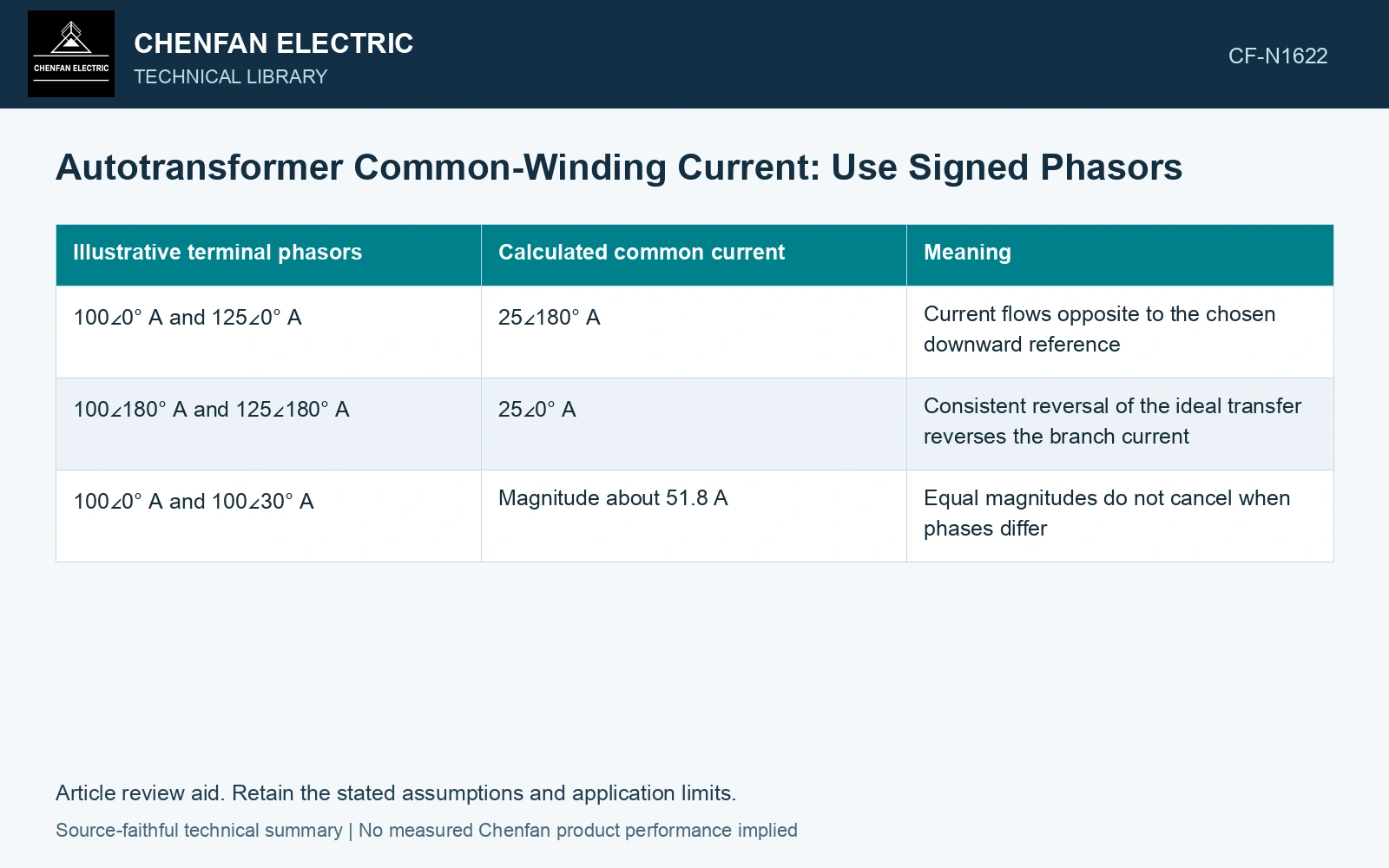
Subtract vectors, not just magnitudes
For phasors IH = Ah exp(jθh) and IL = Al exp(jθl), |IC|² = Ah² + Al² − 2AhAl cos(θh − θl). Currents are in amperes and angles use a consistent convention.
| Illustrative terminal phasors | Calculated common current | Meaning |
|---|---|---|
| 100∠0° A and 125∠0° A | 25∠180° A | Current flows opposite to the chosen downward reference |
| 100∠180° A and 125∠180° A | 25∠0° A | Consistent reversal of the ideal transfer reverses the branch current |
| 100∠0° A and 100∠30° A | Magnitude about 51.8 A | Equal magnitudes do not cancel when phases differ |
The third row is a mathematical phasor illustration, not a proposed operating state for an ideal two-port transformer. The complete network and transformer equations determine which terminal phasors are physically feasible.
Keep the voltage and current references together
Power direction should be determined from complex power under the stated current convention. A negative real power does not mean that a current magnitude becomes negative. Reversing a reference direction changes the phasor sign, while a changing power factor changes its angle.
For balanced three-phase operation, perform the calculation with consistent phase quantities or a justified per-phase model. Do not subtract a line current from a delta winding’s branch current. Connection conversion belongs before the internal-current balance.
Where a tertiary or regulating branch participates, include its connection and ampere-turn relationships. The simple tap-node equation may still hold locally, but the terminal currents no longer follow the unloaded-tertiary ratio alone.
Check the result against internal duty
Compare common-section RMS current with its applicable continuous or short-time limit at the actual tap and cooling condition. Terminal currents within their individual limits do not automatically establish every branch’s margin.
Confirm closure using all three signed branch currents. If it fails, inspect reference direction, channel phase and the connection model before attributing the discrepancy to the transformer. Keep connection, tapping and network assumptions explicit in the application assessment [1].
Report signed port-current phasors with their reference arrows and operating state. Derive the common-winding current from that node balance before using its magnitude for heating or electromagnetic-duty assessment. All numerical inputs and limits in the illustrative cases are assumptions unless a catalogue or standard source is explicitly identified.
Quantify the error from subtracting current magnitudes
The phasor examples are assumptions at 50 Hz. For 100∠0° A and 100∠30° A, vector subtraction gives 51.764 A, while subtracting the magnitudes gives 0 A. For equal 100 A magnitudes with only 5° separation, the result is still 8.724 A. Compare that residual with an assumed 8 A branch limit: the smaller-angle case already reaches 109.0% utilization. Apply this arithmetic to a physically solved operating state and include channel phase uncertainty [2]; it is not a claim that arbitrary phasors satisfy an ideal unloaded-tertiary circuit. Record rated quantities and test conditions on the general power-transformer basis of IEC 60076-1 [3]. Assess the relevant measured quantities with a defined measurement model and propagated uncertainty [2].
References
- IEC, IEC 60076-8:1997, Power transformers – Part 8: Application guide, 1997, official public scope.
- JCGM, JCGM 100:2008, Evaluation of measurement data — Guide to the expression of uncertainty in measurement, 2008.
- IEC, IEC 60076-1:2011, Power transformers – Part 1: General.