

A single winding temperature node assumes that the modeled winding behaves sufficiently uniformly for the requested output. Shell-form groups can have different losses and liquid routes. Their average may be useful for total heat balance while missing the limiting group.
Begin with the physical subdivisions that change heat input or cooling: group position, conductor loss distribution, oil path and contact to neighboring components. Do not create a separate node for every part unless its parameters can be justified.
Write the balance for each retained group
A simplified node equation is Ci dTi/dt = Pi + ΣGij(Tj − Ti), where heat capacity Ci is in joules per kelvin, loss Pi in watts, thermal conductance Gij in watts per kelvin and temperature in kelvins or consistent temperature differences.
Flowing liquid generally needs an appropriate advective energy relation, not merely a symmetric conductance between all oil nodes. State how inlet temperature and branch flow connect to each group.
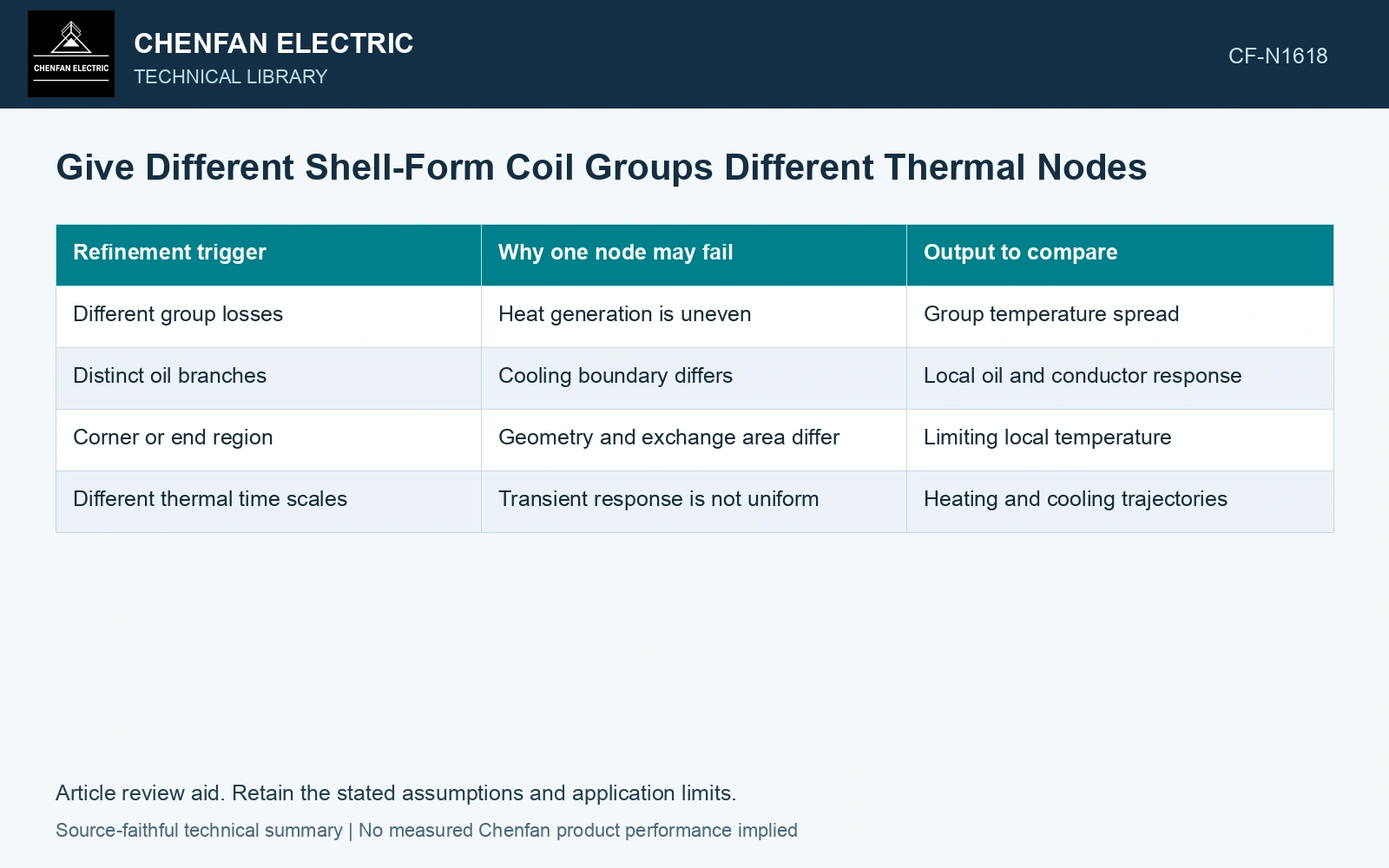
| Refinement trigger | Why one node may fail | Output to compare |
|---|---|---|
| Different group losses | Heat generation is uneven | Group temperature spread |
| Distinct oil branches | Cooling boundary differs | Local oil and conductor response |
| Corner or end region | Geometry and exchange area differ | Limiting local temperature |
| Different thermal time scales | Transient response is not uniform | Heating and cooling trajectories |
Test a merge instead of assuming it
Run a group-resolved model and a proposed merged version with the same total loss and boundary condition. Compare the outputs relevant to the decision, including local maxima and transients. Agreement in average winding temperature does not establish agreement in the hottest group.
Repeat for more than one operating condition if flow or loss distribution changes. A merge that works at one loading state can fail when one group becomes disproportionately heated.
Keep uncertain parameters visible. Increasing node count without measurement support can create many combinations of conductances that fit one temperature record. Use accessible temperature and flow observations to constrain the important paths.
Separate calibration and resolution checks
Do not refit every parameter independently after each merge and then claim that all resolutions agree. That can hide the information lost through merging. First compare them under consistent physical inputs, then assess any justified reduced-model calibration.
Reserve measurements or operating states to challenge the selected model. A temperature point placed in a well-cooled group cannot validate the prediction in an inaccessible weak-flow region by itself. Record rated quantities and test conditions on the general power-transformer basis of IEC 60076-1 [1].
Select the simplest model that preserves the requested local decision within its demonstrated capability. A one-node model may remain appropriate for total cooling duty; a group-resolved model may be needed for a particular hotspot. The distinction follows the output and evidence, not a preference for either simplicity or a larger node count. Assess the relevant measured quantities with a defined measurement model and propagated uncertainty [2].
Show the hotspot hidden by a merged thermal node
Assume a steady two-group model at one specified load and cooling state: each group dissipates 2.0 kW, inlet oil is 60°C, group-to-oil conductances are 100 and 50 W/K, and intergroup heat exchange is neglected. The two rises are P/G = 20 and 40 K, giving 80 and 100°C. A merged model with 4.0 kW and 150 W/K predicts only 86.67°C. It understates the hotter group by 13.33 K despite exact total heat balance. Retain two nodes for a local-temperature decision; a merged node remains a separate approximation for overall cooling duty. Keep mineral-oil loading assessment within its temperature and life-consumption basis [3].
References
- IEC, IEC 60076-1:2011, Power transformers – Part 1: General.
- JCGM, JCGM 100:2008, Evaluation of measurement data — Guide to the expression of uncertainty in measurement, 2008.
- IEC, IEC 60076-7:2018, Power transformers – Part 7: Loading guide for mineral-oil-immersed power transformers.