

A seismic stop allows free relative travel before contact, then transmits load through its attachment. FEMA identifies snubbers and their supports as part of the seismic load path [1]. An always-engaged spring removes the defining gap.
Measure the installed gap and its possible variation
Define the gap in each relevant direction, including tolerance, assembly position and operating movement. Identify the surfaces that meet and the structures behind them. Nominal drawing clearance may not equal the installed clearance at every stop.
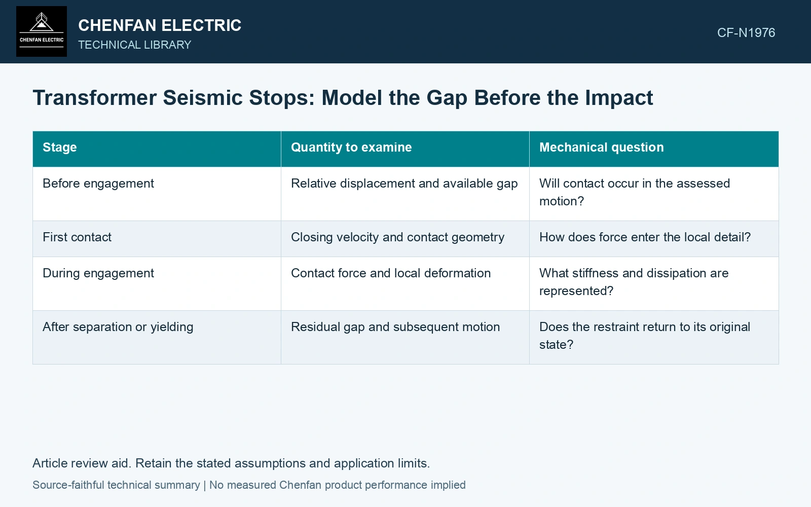
| Stage | Quantity to examine | Mechanical question |
|---|---|---|
| Before engagement | Relative displacement and available gap | Will contact occur in the assessed motion? |
| First contact | Closing velocity and contact geometry | How does force enter the local detail? |
| During engagement | Contact force and local deformation | What stiffness and dissipation are represented? |
| After separation or yielding | Residual gap and subsequent motion | Does the restraint return to its original state? |
Peak force depends on more than the gap
Closing velocity, effective mass, contact stiffness and dissipation govern engagement. Contact changes the motion itself: subtracting the gap from an unconstrained peak does not establish the actual stop compression.
If an impact-capable model is used, inspect time resolution and sensitivity to contact parameters. An artificially stiff contact with inadequate resolution can produce a numerical peak that is mistaken for a physical demand. Conversely, an overly soft representation can conceal local force while permitting unrealistic penetration.
Assess the local force receiver
Trace contact into the stop, its connection and the supporting tank or base structure. Examine the relevant failure mechanisms and whether local plastic deformation is permitted under the project basis. A stop that survives contact may still overload the structure to which it is attached.
Keep physical energy dissipation separate from numerical stabilization and other equivalent damping. If a contact law already dissipates energy, an additional damping assumption needs justification. The same applies to repeated engagement after yielding or separation, where the original gap may have changed.
Assume a single impact with 5 mm initial gap, effective mass 1,000 kg and closing velocity 0.20 m/s. Neglect ongoing base work and damping during compression: kinetic energy ½mv² = 20 J equals ½kδ². At assumed k = 10 MN/m, δ = 2 mm, force 20 kN and total approach 7 mm; at 40 MN/m, δ = 1 mm, force 40 kN and approach 6 mm. Against assumed 7.5 mm travel and 30 kN force caps, the softer candidate passes this screen and the harder fails force. Retain the softer candidate for coupled repeated-contact/attachment qualification. DOE’s equipment guidance stresses a continuous verified load path [2]; the ideal impact calculation does not establish real seismic capacity.
Compare the installed gap with the predicted relative-motion and contact-force histories. If a plausible contact parameter changes the acceptance decision, improve its evidence or retain that sensitivity explicitly. Bounded travel does not establish that the stop and its attachment can carry the engagement force.
References
- FEMA and Applied Technology Council, FEMA E-74, Reducing the Risks of Nonstructural Earthquake Damage—A Practical Guide, December 2012, section 6.4.7.3, Transformers.
- U.S. Department of Energy, DOE-STD-1020-2016, Natural Phenomena Hazards Analysis and Design Criteria for DOE Facilities, 2016, sections 3.5 and 3.6.