

Two transformer configurations can have the same total mass and different centers of gravity. Elevated accessories, oil distribution and active-part position can change overturning or torsional demand without an obvious change in nameplate weight. The mass model should preserve those locations and their uncertainty. [1]
Build the mass inventory in a common coordinate system
List each relevant component with mass, center coordinates and the basis of that information. Distinguish measured values, controlled drawing values and estimates. Avoid counting tank oil both as a separate entry and within an already filled equipment mass.
For discrete components, the combined center coordinate is xG = Σ(mixi)/Σmi; the same relation applies to y and z. Use consistent units and a defined origin. This bookkeeping relation does not by itself determine dynamic participation or fluid coupling.
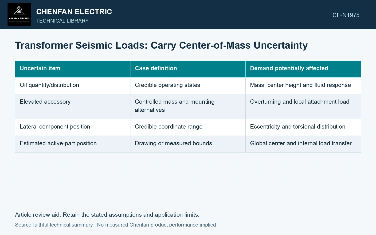
| Uncertain item | Case definition | Demand potentially affected |
|---|---|---|
| Oil quantity/distribution | Credible operating states | Mass, center height and fluid response |
| Elevated accessory | Controlled mass and mounting alternatives | Overturning and local attachment load |
| Lateral component position | Credible coordinate range | Eccentricity and torsional distribution |
| Estimated active-part position | Drawing or measured bounds | Global center and internal load transfer |
Preserve physically compatible cases
A maximum mass and maximum center height may not belong to the same equipment state. Construct credible configurations rather than independently maximizing every input without checking compatibility. If a deliberately conservative envelope is used, label how it differs from an achievable configuration.
In a simplified inertial illustration, a horizontal resultant F acting at height h creates moment Fh about a base reference. This shows the role of center height; it is not a full anchorage calculation. Dynamic modes, vertical demand, support contact and connection geometry still govern the project assessment. [2]
Compare the demand distribution, not only the total moment
Carry each justified mass case into the appropriate structural model. Compare demands at individual anchors and attachments, since a lateral center shift can redistribute load between them. The largest equipment resultant need not identify the most heavily loaded individual connection.
Assume operating mass 20,000 kg and horizontal acceleration 0.5g with g = 9.81 m/s²: force is 98.1 kN. Credible assumed centre heights 1.5/1.8 m give overturning moments 147.15/176.58 kN·m. Against an assumed 160 kN·m overall review cap the lower estimate passes and the upper fails. Resolve the actual mass locations or advance the upper credible case before anchor design; unchanged total mass and geometric tank centre cannot close this 20% demand range.
Record which uncertain item controls each demand and whether better information could change the decision. A component inventory with traceable bounds is more useful than a center coordinate reported to many decimal places. It allows later accessory or oil-state changes to be checked against the same mass basis.
References
- IEEE, IEEE 693-2018, IEEE Recommended Practice for Seismic Design of Substations.
- FEMA and Applied Technology Council, FEMA E-74, Reducing the Risks of Nonstructural Earthquake Damage—A Practical Guide, December 2012, section 6.4.7.3, Transformers.