

A transformer base may transfer force through friction and an engaged shear key. DOE’s equipment guidance calls for a continuous traceable load path [1]. Compare the mechanisms at compatible displacement/contact states before crediting their sum.
Describe the engagement sequence
Record the initial key clearance, contact surfaces, base clamping condition and direction of movement. A key separated by a gap cannot develop bearing force before the gap closes. A friction interface can change behavior as slip begins or normal contact changes. Their sequence matters to the connection demand. [1]
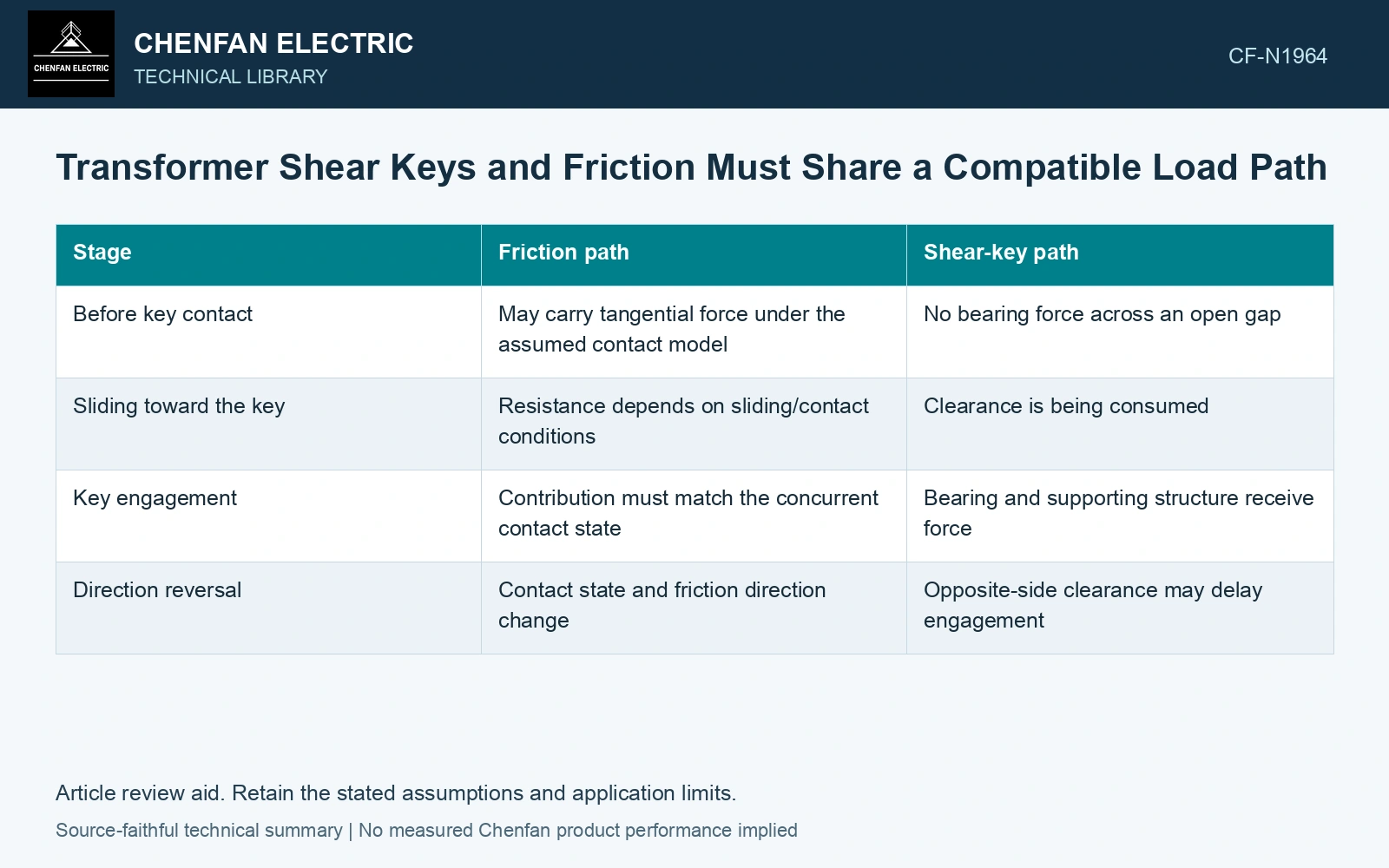
| Stage | Friction path | Shear-key path |
|---|---|---|
| Before key contact | May carry tangential force under the assumed contact model | No bearing force across an open gap |
| Sliding toward the key | Resistance depends on sliding/contact conditions | Clearance is being consumed |
| Key engagement | Contribution must match the concurrent contact state | Bearing and supporting structure receive force |
| Direction reversal | Contact state and friction direction change | Opposite-side clearance may delay engagement |
Check where the key sends its force
Trace base force through key, welds/fasteners and receiving concrete/steel. Contact/clamping conditions affect friction; NASA’s fastener manual discusses these joint dependencies [2]. A strong key does not establish its attachment capacity.
Under reversal, check whether the same key face or another face engages and whether the clearance changes the response. A linear restraint active in both directions from zero displacement may not represent a detail intended to engage after movement.
Compare mechanisms at common displacement states
Evaluate the assumed contributions using a compatible force-displacement description. If friction is credited before key engagement, show what remains when the key engages. If a combined capacity is used, establish that the physical and design assumptions allow the mechanisms to coexist at the necessary displacement.
Do not choose a friction coefficient, gap or impact multiplier merely to make the combined result pass. Each belongs to the actual support/detail definition and the accepted assessment method. Where contact impact matters, retain its model limits and sensitivity rather than substituting an arbitrary static amplification.
Assume normal contact force 100 kN and friction coefficient 0.20: friction screen is 20 kN. At concurrent 50 kN horizontal demand, an engaged key takes 30 kN. If uplift reduces normal force to assumed 40 kN, friction is 8 kN and key demand 42 kN. Against an assumed 35 kN key-capacity screen, the first state passes and the uplift state fails. Evaluate actual engagement/impact and attachment strength; full fixed-base friction is unavailable after normal force is lost.
Identify the restraint that carries force before slip and the restraint that carries it after key engagement. If the key receives the remaining load, check its attachment under that demand. Adding two nominal capacities obscures this sequence and can credit resistance that the connection never develops simultaneously.
References
- U.S. Department of Energy, DOE-STD-1020-2016, Natural Phenomena Hazards Analysis and Design Criteria for DOE Facilities, 2016, sections 3.5 and 3.6.
- R. T. Barrett, Fastener Design Manual, NASA Reference Publication 1228, 1990.