

An anchor connection transfers force into a volume of concrete, not into an abstract support point. Closely spaced anchors, nearby edges and the reinforcement layout can change the potential failure path. Checking the bolt steel alone leaves that part of the transformer load path unresolved. [1] [2]
Begin with the installed anchor-group geometry
Record anchor locations, embedment, edge distances, spacing, foundation dimensions and the verified concrete condition. Distinguish design drawings from as-built evidence. A nominal foundation size does not establish that every anchor has the intended embedment or that the reinforcement is positioned as assumed.
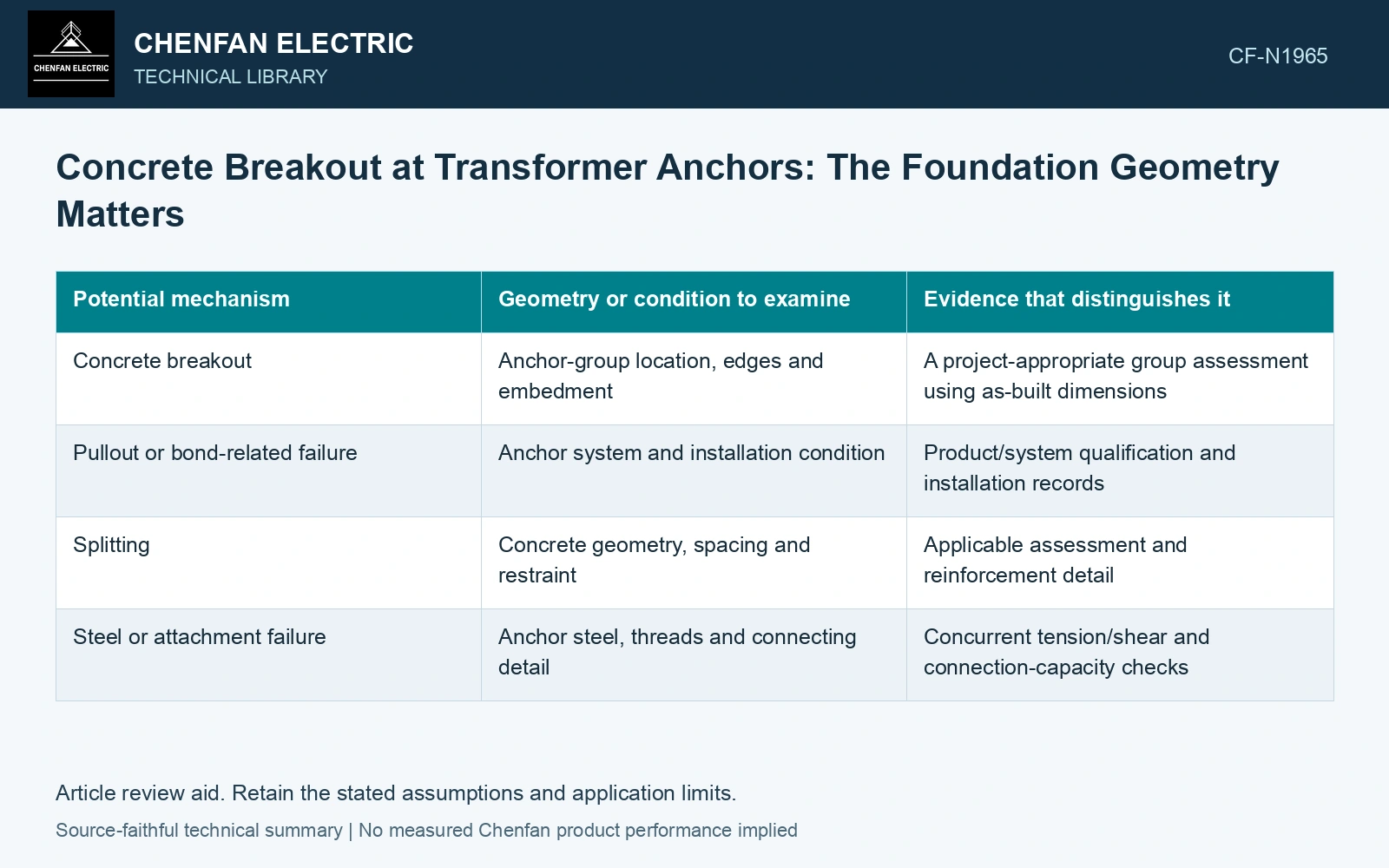
| Potential mechanism | Geometry or condition to examine | Evidence that distinguishes it |
|---|---|---|
| Concrete breakout | Anchor-group location, edges and embedment | A project-appropriate group assessment using as-built dimensions |
| Pullout or bond-related failure | Anchor system and installation condition | Product/system qualification and installation records |
| Splitting | Concrete geometry, spacing and restraint | Applicable assessment and reinforcement detail |
| Steel or attachment failure | Anchor steel, threads and connecting detail | Concurrent tension/shear and connection-capacity checks |
Reinforcement needs a demonstrated path
Reinforcement can only be credited according to the applicable design method and an actual detail that develops the required force. A note saying the foundation is reinforced does not show which bars intercept the potential failure region, how they are developed or whether they were installed in the required position.
Review the anchor demand from the equipment model at the relevant load combinations and connection states. Unequal tension, uplift and shear can change which anchors are active. Passing an equal-share force to the foundation designer without the equipment assumptions can conceal a concentrated demand.
Keep code capacity separate from a conceptual failure sketch
A sketch of candidate breakout surfaces helps explain the geometry. It does not replace the equations, factors and limits of the governing project rules. Use the required current standard, amendment and local adoption where applicable; a historical guidance example cannot supply current capacity values for another jurisdiction.
Where the as-built detail is uncertain, identify the information required to resolve it through an appropriate inspection or investigation plan. Do not infer hidden embedment or reinforcement solely from the visible anchor position.
Assume group demand 120 kN. An initial equal-share ledger assigns 30 kN to four anchors. Suppose a fictional project group calculation including edges/overlap gives resistance 100 kN: utilisation is 1.20. Incorrectly summing four assumed isolated ratings of 40 kN gives 0.75 and a false pass. These resistance values are assumptions, not calculations from FEMA or IEEE. DOE’s load-path framework also requires capacity assessment of the receiving structure [3]. Obtain the actual qualified anchor/concrete group calculation with as-built embedment and edges before choosing an upgrade.
A satisfactory bolt-strength result can leave concrete breakout, pullout or another mechanism unresolved. Follow the controlling demand to the evidence it needs: installed geometry, a qualified anchor system or reinforcement details. Revise the connection when that evidence cannot establish the required load path.
References
- FEMA and Applied Technology Council, FEMA E-74, Reducing the Risks of Nonstructural Earthquake Damage—A Practical Guide, December 2012, section 6.4.7.3, Transformers.
- IEEE, IEEE 693-2018, IEEE Recommended Practice for Seismic Design of Substations.
- U.S. Department of Energy, DOE-STD-1020-2016, Natural Phenomena Hazards Analysis and Design Criteria for DOE Facilities, 2016, sections 3.5 and 3.6.