

A transformer’s tank and active part need not respond as one perfectly rigid mass. Internal supports, clamps and stops determine how core-and-coil inertia reaches the enclosure and foundation. An external anchorage check leaves that internal path unresolved if those interfaces are omitted. [1] [2]
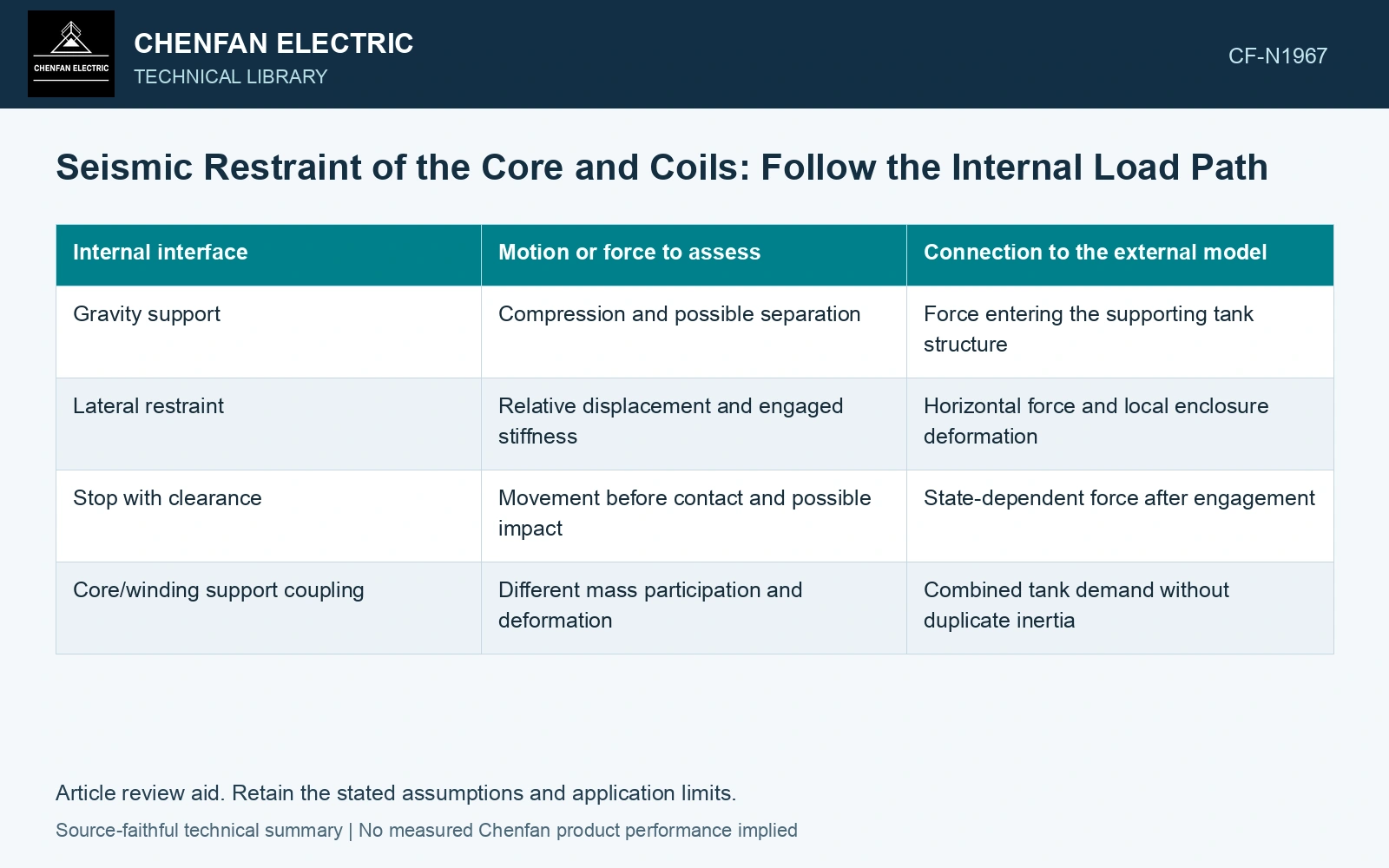
Separate the active-part masses and interfaces
Identify the mass distribution of the core, windings and relevant internal structures. Mark their support locations, restraints, permitted movement and any initial gaps. Distinguish a gravity support from a restraint capable of transferring horizontal or uplift force.
| Internal interface | Motion or force to assess | Connection to the external model |
|---|---|---|
| Gravity support | Compression and possible separation | Force entering the supporting tank structure |
| Lateral restraint | Relative displacement and engaged stiffness | Horizontal force and local enclosure deformation |
| Stop with clearance | Movement before contact and possible impact | State-dependent force after engagement |
| Core/winding support coupling | Different mass participation and deformation | Combined tank demand without duplicate inertia |
Relative motion is the discriminating result
Evaluate displacement between the active part and its support, not only the absolute tank displacement. A small tank response can coexist with significant internal motion if a support is flexible or a restraint engages after a gap. Conversely, treating every internal mass as freely moving would ignore the connections that actually restrain it.
Retain the coupling between the equipment model and the local connection model. If internal inertia is included in the global mass, do not add an independently calculated full inertial force to the same connection without a consistent load-transfer definition.
Check engagement and local consequences
Where stops or clearances exist, establish the intended sequence of movement and contact. Review the local surfaces and structures that receive the force. A stop can limit travel while creating a concentrated connection demand; limiting movement is not proof that all stressed parts remain acceptable.
The applicable seismic input and equipment configuration should govern the assessment. Shipping acceleration and restraint arrangements may provide useful information about a different duty, but they cannot be substituted automatically for seismic motion and installed support conditions.
Assume internal active-part mass 12,000 kg and horizontal acceleration 0.5g with g = 9.81 m/s²: restraint resultant is 58.86 kN. Four equally engaged supports carry 14.715 kN each; if only two engage, each carries 29.43 kN. Against an assumed 20 kN-per-support capacity screen, four pass and two fail. Hold the equal-share model until actual gaps, stiffness and core/coil restraint are established. A passing external anchor check does not close the internal path or justify adding duplicate inertia.
Follow an internal mass through each engaged support to the tank. An unassigned interface is a missing part of the load path, even when the external anchors have been checked. Relative motion and local connection demand determine whether that internal restraint is represented adequately.
References
- FEMA and Applied Technology Council, FEMA E-74, Reducing the Risks of Nonstructural Earthquake Damage—A Practical Guide, December 2012, section 6.4.7.3, Transformers.
- IEEE, IEEE 693-2018, IEEE Recommended Practice for Seismic Design of Substations.