

Rocking separates compression-only bearing from tension-capable restraints. FEMA identifies sliding/overturning and internal inertia [1]; DOE requires a continuous load path [2]. A fixed footprint can conceal an unavailable tensile bearing reaction.
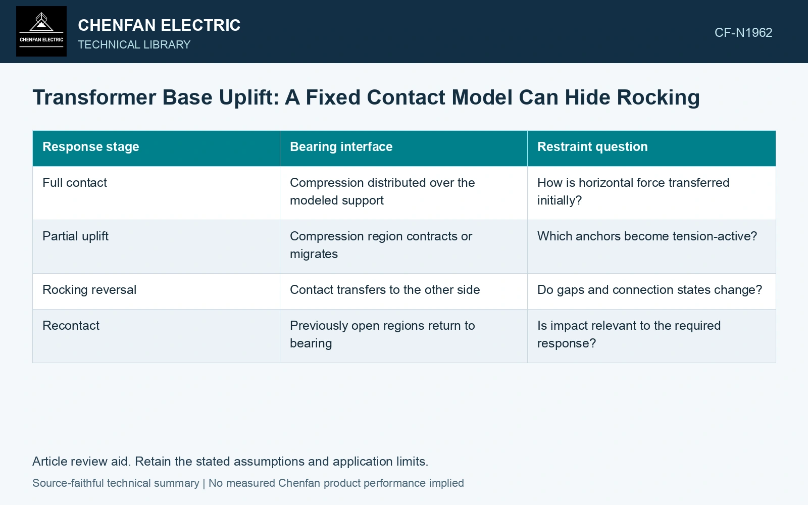
Separate contact from the tensile restraint
Represent bearing, anchors and any other restraint as distinct interfaces. Define initial gaps, support elevation, base stiffness and the tension-capable connections. If a contact region opens, the anchors or other restraints must carry the corresponding tensile demand according to their actual arrangement.
| Response stage | Bearing interface | Restraint question |
|---|---|---|
| Full contact | Compression distributed over the modeled support | How is horizontal force transferred initially? |
| Partial uplift | Compression region contracts or migrates | Which anchors become tension-active? |
| Rocking reversal | Contact transfers to the other side | Do gaps and connection states change? |
| Recontact | Previously open regions return to bearing | Is impact relevant to the required response? |
Read the reactions together with the changing contact area
Plot contact pressure and open regions over the relevant loading history. Compare anchor tension, baseplate deformation and foundation demand at the same states. Selecting the maximum of each output without its associated configuration can assemble an impossible combination or conceal the actual critical load path.
A linear fixed-base reference remains useful for comparison, provided its limitation is visible. Look for tensile reactions attributed to contact-only regions. Those reactions identify where the idealization needs review; they are not tensile bearing capacities that can be passed to the civil designer.
Do not replace the dynamic problem with a static footprint check
The center-of-mass projection and a static overturning moment provide useful geometry information, but they do not reproduce evolving contact, anchor engagement or dynamic recontact. The necessary model depends on whether those mechanisms materially affect the required response.
Investigate sensitivity to support unevenness, contact stiffness, anchor representation and credible initial gaps. Numerical contact settings should have a physical basis and suitable stability checks. A very stiff contact can produce a sharp numerical force whose interpretation requires more than reading the maximum stress color.
Assume rigid base, vertical load N = 200 kN and support width B = 2.0 m. A linear full-contact pressure screen first requires |e| = |M/N| ≤ B/6 = 0.333 m. At M = 120 kN·m, e = 0.60 m: full contact is lost although a partial compression region may still equilibrate it. At assumed M = 240 kN·m, e = 1.20 m exceeds the 1.0 m half-width; compression-only bearing cannot balance the resultant at all. In an ideal two-edge load path, equilibrium needs 220 kN compression at one edge and 20 kN tension at the other. Provide/qualify that tension path and actual base/contact geometry; these are equilibrium screens, not a dynamic rocking or anchor-capacity solution.
If contact opening changes which anchors carry tension, the fixed-base approximation needs justification for that load state. Keep the contact sequence beside the corresponding connection demands. An uplift limit alone cannot establish anchorage adequacy without the capacity and installation assessment.
References
- FEMA and Applied Technology Council, FEMA E-74, Reducing the Risks of Nonstructural Earthquake Damage—A Practical Guide, December 2012, section 6.4.7.3, Transformers.
- U.S. Department of Energy, DOE-STD-1020-2016, Natural Phenomena Hazards Analysis and Design Criteria for DOE Facilities, 2016, sections 3.5 and 3.6.