

Anchor pretension can affect when a transformer base slips or separates. The assumed clamping state therefore belongs in the load-path model, not only in an installation instruction. If the model relies on friction maintained by pretension, the evidence must support that pretension under the relevant conditions. [1] [2]
Distinguish a setting from a verified force
Record the anchor type, installation method, assumed pretension, support condition and verification basis. Torque is influenced by thread and bearing friction; it should not be silently relabeled as measured bolt tension. Grout, connection seating and subsequent changes can affect the retained state.
Identify whether the design intends horizontal force to pass through contact friction, anchor shear, a shear key or a combination. These mechanisms can become active at different displacements. The contribution assigned to each must be compatible with the modeled motion and actual installation.
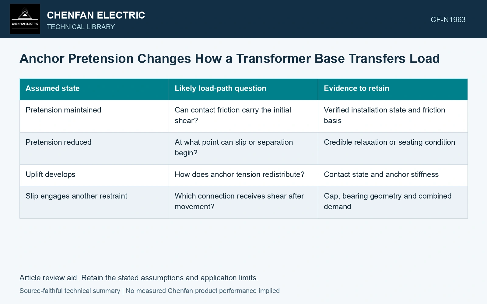
| Assumed state | Likely load-path question | Evidence to retain |
|---|---|---|
| Pretension maintained | Can contact friction carry the initial shear? | Verified installation state and friction basis |
| Pretension reduced | At what point can slip or separation begin? | Credible relaxation or seating condition |
| Uplift develops | How does anchor tension redistribute? | Contact state and anchor stiffness |
| Slip engages another restraint | Which connection receives shear after movement? | Gap, bearing geometry and combined demand |
Do not combine incompatible maxima
Evaluate the relevant tension and shear at the same connection state. A friction capacity based on full compression may be unavailable when uplift reduces the contact region. Likewise, the most highly tensioned anchor need not receive the shear distribution assumed by an equal-share calculation.
For a conceptual friction interface, transferable tangential force depends on the chosen friction model and effective compressive contact force. That relationship identifies a required input; it does not justify a universal coefficient or a field installation relying on friction without project approval.
Use pretension uncertainty as a model case
Compare the intended installation state with a credible lower retained state. Examine slip, uplift, anchor force and any secondary restraint engagement. If modest changes in pretension alter the load path substantially, the installation verification and monitoring requirements become influential design inputs.
Assume four anchors retain 50 kN each, giving 200 kN additional interface clamp. At assumed μ = 0.20 the additional friction screen is 40 kN; retaining only 30 kN each gives 24 kN. In an isolated comparison neglecting self-weight and other normal loads, an assumed 30 kN shear demand passes the first and fails the second. Verify retained force and concurrent separation before crediting it. The real interface normal force must include self-weight/uplift consistently; this clamp-only example is not an installed anchorage qualification.
The assumed clamping state must be achievable by the installation procedure and verifiable to the required extent. If field access prevents verification, retain that uncertainty in the assessment. A torque value on a drawing is useful process information; it is not a measured seismic connection state.
References
- FEMA and Applied Technology Council, FEMA E-74, Reducing the Risks of Nonstructural Earthquake Damage—A Practical Guide, December 2012, section 6.4.7.3, Transformers.
- R. T. Barrett, Fastener Design Manual, NASA Reference Publication 1228, 1990.