

A fixed-base model omits foundation translation/rocking. DOE’s response-analysis framework distinguishes foundation input and structural response [1]; define the coupled boundary before evaluating connection capacity.
Use a small model to expose the assumption
For an illustrative one-dimensional system, let equipment stiffness be kₑ and foundation stiffness be k𝒻, both in N/m, connected in series beneath a lumped mass m in kg. The equivalent stiffness is k = (1/kₑ + 1/k𝒻)⁻¹ and the natural frequency is f = √(k/m)/(2π), in Hz. A rigid-foundation limit gives k → kₑ.
This simple model shows why adding support compliance can reduce the frequency relative to the fixed-base idealization. It does not represent foundation rocking, distributed mass, soil nonlinearity or frequency-dependent impedance. Use it to identify a potentially important boundary condition, then select the model needed for the actual decision.
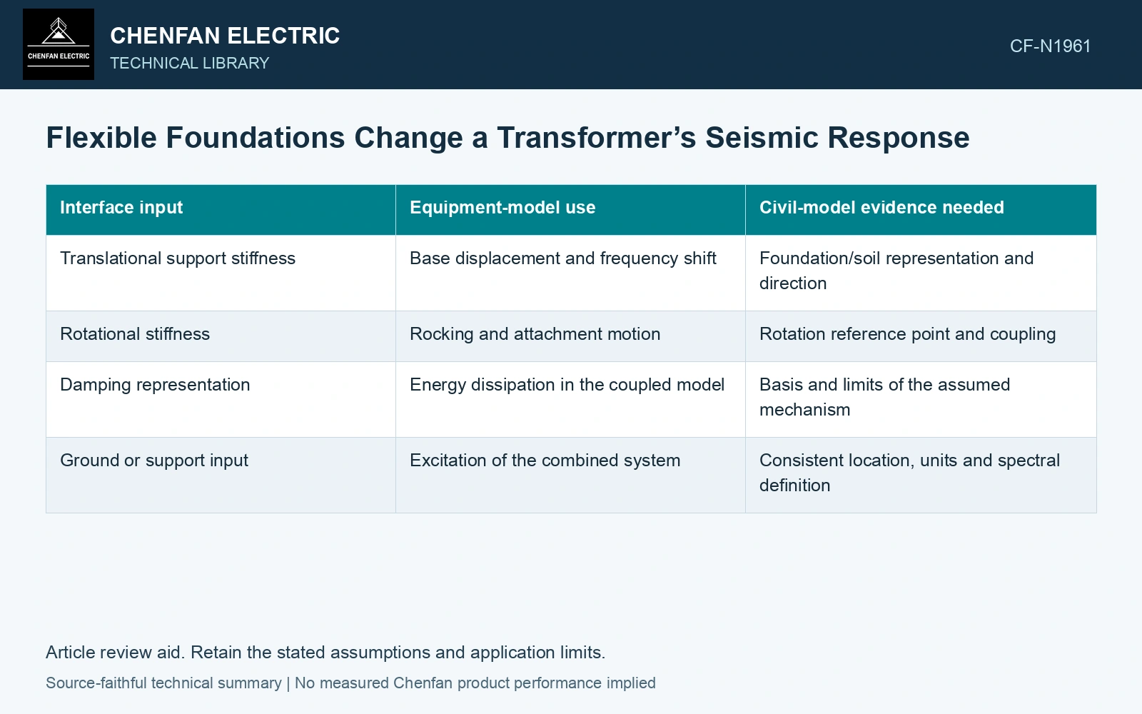
| Interface input | Equipment-model use | Civil-model evidence needed |
|---|---|---|
| Translational support stiffness | Base displacement and frequency shift | Foundation/soil representation and direction |
| Rotational stiffness | Rocking and attachment motion | Rotation reference point and coupling |
| Damping representation | Energy dissipation in the coupled model | Basis and limits of the assumed mechanism |
| Ground or support input | Excitation of the combined system | Consistent location, units and spectral definition |
A lower frequency does not guarantee lower demand
Read the changed physical modes against compatible input and response-combination definitions [2]. A lower frequency may move toward higher or lower demand; it is not a benefit by itself.
Check whether the chosen equipment and civil representations double-count foundation flexibility or omit it. An equipment model that already includes support springs should not be combined with a support motion generated using the same compliance without a consistent coupling definition.
Compare the boundaries with the same equipment configuration
Run a fixed-base reference and a justified flexible-base case using the same mass, accessories and input definition. Identify which response quantities change materially. Retain the coordinates and connection loads needed for the foundation and anchor assessment.
Assume equipment/foundation stiffnesses 20/20 MN/m and effective mass 10,000 kg. Series stiffness 10 MN/m gives f = 5.03 Hz; rigid foundation gives 7.12 Hz. Assume a compatible one-mode spectrum has acceleration ordinates 1.2g and 0.8g at these frequencies, respectively, with unit participation. Force screens are 117.72 and 78.48 kN. Against an assumed 100 kN connection cap, the flexible case fails while the rigid reference passes. Use site-supported stiffness/input and preserve uplift/contact if governing; a 29.3% frequency reduction does not establish reduced demand.
Resolve foundation stiffness and interface motion before relying on the equipment stress plot. Assign each influential input to the party that can establish it, then rerun the coupled case if that input changes. Historical anchorage guidance and a standard catalogue do not supply the project soil stiffness or establish acceptance of the installed assembly.
References
- U.S. Department of Energy, DOE-STD-1020-2016, Natural Phenomena Hazards Analysis and Design Criteria for DOE Facilities, 2016, sections 3.5 and 3.6.
- U.S. Nuclear Regulatory Commission, Regulatory Guide 1.92, Combining Modal Responses and Spatial Components in Seismic Response Analysis, Revision 3, October 2012, sections C.1.1 and C.2.