

A multi-core CT can pass several electrical tests and still have a terminal-identification error. Two cores may use the same nominal ratio while serving different protection or metering duties. If their leads or labels are exchanged, a test report organized only by ratio may never expose the swap. [1]
End-of-line verification should connect four records: physical core identity, secondary winding route, actual terminal combination and the result measured on that combination. [2]
Build the map before closing the assembly
Assign a traceable manufacturing identity to each core and winding. This can be a serial number or an approved assembly identifier; it need not be an impractical marking on every magnetic strip. Preserve the identity as the winding is made, its leads are routed and the assembly becomes inaccessible.
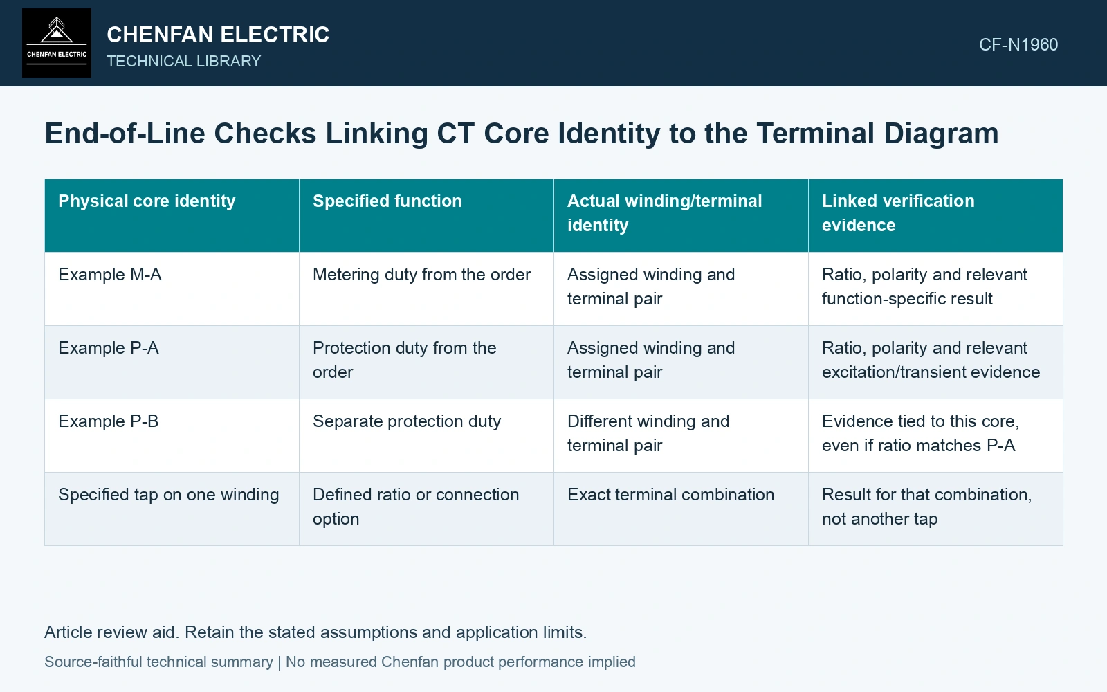
| Physical core identity | Specified function | Actual winding/terminal identity | Linked verification evidence |
|---|---|---|---|
| Example M-A | Metering duty from the order | Assigned winding and terminal pair | Ratio, polarity and relevant function-specific result |
| Example P-A | Protection duty from the order | Assigned winding and terminal pair | Ratio, polarity and relevant excitation/transient evidence |
| Example P-B | Separate protection duty | Different winding and terminal pair | Evidence tied to this core, even if ratio matches P-A |
| Specified tap on one winding | Defined ratio or connection option | Exact terminal combination | Result for that combination, not another tap |
The example labels have no implied terminal standard. Use the approved diagram’s actual identifiers.
Check a complete chain, not two disconnected lists
A core inspection list and an electrical test list can each be complete while their relationship is wrong. Reconcile them through the winding route and actual terminal identity. Manufacturing photographs or lead-routing records can support the hidden portion of the chain; electrical verification supports the accessible endpoints.
A matching ratio proves neither functional identity nor unique origin when several cores share that ratio. Relevant excitation or other function-specific evidence can help distinguish cores, but it should be interpreted against the specified construction and test method. Avoid treating an incidental difference between two curves as the sole identity mark.
Resolve inconsistencies at their first uncertain link
If a terminal result matches the wrong function, examine whether the physical core identity, lead route, diagram or test label is incorrect. Changing the label to fit the result without checking the hidden route can conceal an assembly error.
For tapped windings, retain the tested terminal combination and polarity reference. A correct result on one pair cannot validate every alternative connection. Diagram revisions after repair or retermination require the mapping to be updated as well.
Assume two cores M/P both specified 1,000/1 A. Controlled 100 A primary injection gives ideal 0.100 A at each secondary, so swapping terminal routes leaves both ratio checks passing [1]. In a separate controlled de-energised secondary-excitation comparison, assume reference currents at 10 V RMS, 50 Hz are 20 mA for M and 5 mA for P, with expanded uncertainty ±0.5 mA. Finding 5 mA on labelled M and 20 mA on P exposes a function-map discrepancy; it does not prove physical identity from one curve [2]. Hold release, trace the hidden lead/core records and correct the controlled map [3], then complete the specified function/accuracy/polarity tests.
The final record should leave each specified core function with one unambiguous terminal destination and its own evidence. That is the end-of-line control that prevents a collection of good cores from becoming a CT with the wrong function available at the labelled terminals.
References
- ABB, Instrument Transformers Application Guide, publication 1HSM 9543 40-00en, Edition 4, February 2015, sections 3.4 and 4.9–4.12.
- ABB, Instrument Transformers: Technical Information and Application Guide, 1VAP420003-TG, revision A, December 2004.
- NASA, NASA Systems Engineering Handbook, section 6.5, Configuration Management, official online text.