

Classify transport-related parts from the actual drawing. ABB describes permanent quartz filling supporting the active assembly during transport in one hairpin construction [1]; that is not a removable shipping fixture. Check the unit’s specified shipping-to-service configuration transition [2].
Some designs have no removable internal restraint at all. The first verification is therefore whether the particular unit contains one, where it is located and which state the manufacturer requires for service.
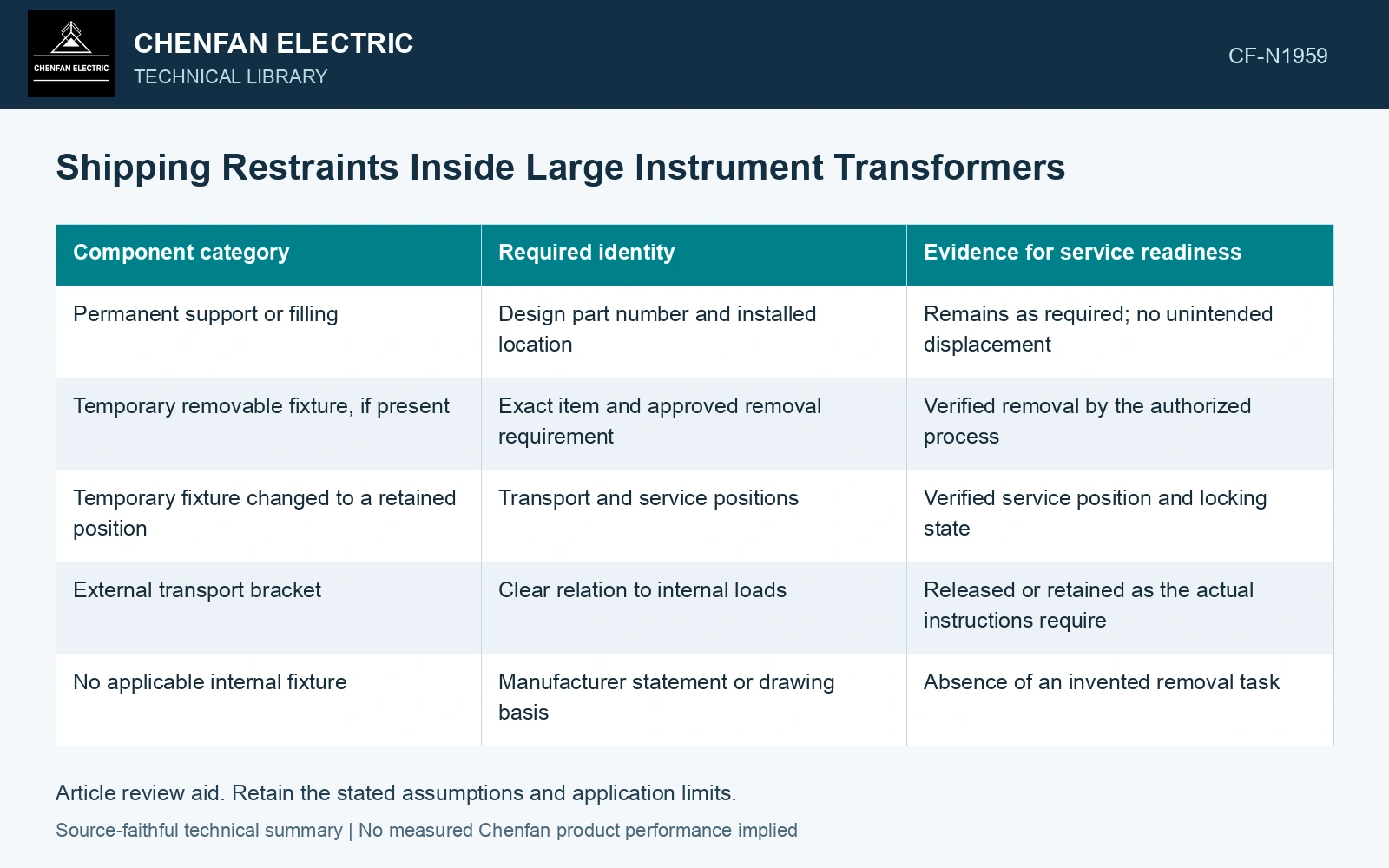
Classify each transport-related component
Give every relevant item a unique drawing identity and state requirement. Avoid a generic note such as ‘remove shipping supports’ when permanent and temporary items appear similar. For a sealed instrument transformer, an ambiguous note can encourage unnecessary opening or leave an internal fixture in the wrong state.
| Component category | Required identity | Evidence for service readiness |
|---|---|---|
| Permanent support or filling | Design part number and installed location | Remains as required; no unintended displacement |
| Temporary removable fixture, if present | Exact item and approved removal requirement | Verified removal by the authorized process |
| Temporary fixture changed to a retained position | Transport and service positions | Verified service position and locking state |
| External transport bracket | Clear relation to internal loads | Released or retained as the actual instructions require |
| No applicable internal fixture | Manufacturer statement or drawing basis | Absence of an invented removal task |
Connect restraint state to insulation geometry
A temporary fixture can affect a clearance or load a winding/screen. Tie its required service state to the actual drawing-controlled interfaces and retain evidence of the approved transition [2]. A checked box alone does not establish those clearances.
Removal does not by itself prove the supported assembly stayed in position. Review the relevant post-transport position evidence, particularly where transit loads could shift a heavy core or active part. The appropriate observation depends on the sealed construction; it need not imply direct internal access on every unit.
Keep inaccessible evidence honest
Factory photographs, position marks, approved internal observations and electrical tests can support different aspects of the final state. None automatically substitutes for another. A terminal-level electrical test may reveal a change without locating it, while a photograph taken before dispatch cannot show a later movement.
Where an internal item cannot be observed at receipt, state how the manufacturer establishes its condition and which evidence applies to the unit. Do not open a sealed assembly simply to satisfy a generic checklist created for another transformer.
Assume a shipping-supported assembly weighs 80 kg and the agreed acceleration screen is 3g: demand is 2,354.4 N. Two equal restraints carry 1,177.2 N each. With assumed capacity 1,500 N each, two pass; one loose restraint leaves the other carrying 2,354.4 N and failing. Verify the installed load path and its prescribed service transition. This transport screen neither qualifies dielectric/thermal service nor authorises removal of a permanent support.
The receiving record should reconcile the shipment configuration, required service configuration and the actual evidence of transition. That makes the restraint question specific to the equipment, while avoiding both an overlooked temporary fixture and an unnecessary intervention on permanent insulation or support structures.
References
- ABB, Instrument Transformers Application Guide, publication 1HSM 9543 40-00en, Edition 4, February 2015, sections 5.1–5.6, 6.1 and 7.1.
- NASA, NASA Systems Engineering Handbook, section 6.5, Configuration Management, official online text.